Photosensors
Photosensors are classed by the physical quantity that is affected by the
light, and the main classes are photoresistors, photovoltaic materials, and photoemitters. Historically, photoemitters have been more important in unravelling the theory of the effect of light on materials, but photovoltaic materials, notably selenium, were in use for some considerable time before the use of photoemission became practicable. Since photoemission allows us to combine the description of a usable device with the quantum effect, we will consider this type of sensor first, which can also be used to a limited extent as a transducer. The photoemissive cell, in fact, was the dominant type of photosensor for many years, and played a vital part in the develop- ment of cinema sound since it was the transducer first used for converting the film soundtrack into audio-electrical signals.
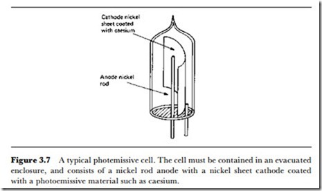
A simple type of photoemissive cell is illustrated in Figure 3.7. This is a vacuum device, because the photoemissive material is one that oxidizes instantly and violently in contact with air, and even in quite low pressures it will oxidize sufficiently to prevent any photoemission. The photoemissive action is the release of electrons into the surrounding vacuum when the material is struck by light. This release of electrons will take place whether the electrons have anywhere to go or not, but unless there is a path provided, all the electrons will lose energy and return to the emitting surface, often termed the photocathode. By enclosing another metal – a nickel wire, for example – which is at a voltage more positive than the photocathode, the cell can be used as part of a circuit in which current will flow when light strikes the photocathode. When light releases electrons, the current that flows is proportional to the amount of energy carried by the
light beam. This, however, is true only if the light is of a frequency that will release electrons. For any photoemitting material there will be a threshoLd frequency of light. Below this threshold frequency, electrons will not be emitted no matter how intense the light happens to be, so that, in general, photoemitters do not respond to infrared, particularly the far infrared. The explanation of this threshold effect is due to Einstein, and makes use of an idea that was earlier put forward by Planck.
Planck’s theory was that energy existed in units just as materials exist in atoms, and he named the unit the quantum. The quantum is a unit of action, a physical quantity that was not considered of practical interest prior to Planck’s theory. The size of the quantum for a light beam is equal to the frequency of the light multiplied by a constant that we now call Planck’s constant. We touched on this idea when considering laser interferometry, because the factor that prevents light from most sources from being coherent is that it is given out in these quantum-sized packets rather than as a truly continuous beam.
Einstein reasoned that the size of the quantum affected the separation of an electron from an atom in a photoemitter, and if the amount of energy carried in one quantum was less than the amount of energy needed to separate an electron, then no separation would take place. The total amount of energy carried by the beam was of no importance if the units of energy were insufficient to separate the electrons. The theory was confirmed by experiment, and this work also established Planck’s quantum theory as one of the main supports of modern physics.
The practical effect as far as we are concerned is that photoemissive cells have a limited range of response, and whereas it is easy to make cells that sense ultraviolet light (high frequency), it is much more difficult to prepare materials that will sense infrared. Most photocells are noticeably much
more sensitive to light in the bluejviolet end of the spectrum than in the orangejred end. Mixed photocathode materials containing antimony along with the alkali metals caesium, potassium and sodium, have been the most successful emitters in terms of providing an electrical output that is reason- ably well maintained for the visible frequencies of light. This does not imply, however, that the output is by any means uniform.
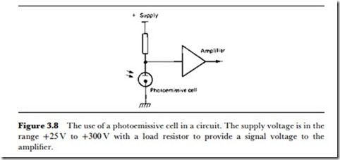
The photoemissive cell is used in a circuit of the type shown in Figure 3.8, with a voltage supply that is often in the region of 25-100 V between anode and cathode. Some circuits make use of the current through the cell directly, but the most common circuit is as shown here, using a load resistor in series with the cell and amplifying the voltage signal. This is particularly useful when the incoming light is modulated in some way so that the electrical output will be an AC signal, such as that in use as a cinema soundtrack transducer.
Where a DC output is needed, the use of a photoemitter is less simple, and a current amplifier is more useful than a load resistor and voltage amplifier. The current through a typical cell is of the order of a microamp, so that fairly large load resistors and a considerable amount of amplification will be needed. This creates difficulties with both frequency response and noise level when the photocell is used to convert modulated light signals into AC signals.
For measuring purposes, any photoemitter detector will have to be cali- brated for each light colour for which it will be used, and if a reasonably high precision is needed, this calibration will be a long and tedious matter. It is important to realize that ‘white’ light is a mixture of all the frequencies of the visible spectrum, and can also contain a proportion of invisible ultra- violet. This means that imperceptible changes in the composition of ‘white’ light which have no effect on its total energy will nevertheless have very large effects on the output from a photoemissive cell. This is, in fact, something that affects most photosensitive devices, as keen photographers will know.
Comparisons of light levels must therefore be made only when the compo- sition of light is constant, and this is something that is very difficult to achieve, particularly for natural lighting. For artificial lighting using fluorescent tubes, constant light composition is much easier to achieve, but filament lamps give a light that contains a large fraction of red light and for which the light composition varies very sharply as the voltage is altered. A filament lamp which is run below its rated voltage gives light that is predominantly red; when run above its rated voltage it can give light that is biased to the blue end of the spectrum (with a greatly reduced life).
Photoemitters are still used where a fast response is needed, because many competing devices are solid-state rather than high-vacuum, and the speed of electrons in a solid is very much lower than the speeds that can be obtained in a vacuum. Even for cinema soundtracks, however, the vacuum photocell has now been replaced, and at the time of writing, vacuum devices are found only in old equipment and in instruments intended for specialized use. For these reasons, then, more detailed descriptions of vacuum photoemissive cells will not be given here. However, the photomul- tiplier obtains very much greater sensitivity from a photocell at very little cost in noise or time delay.
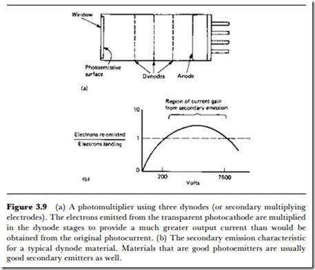
The principle, illustrated in Figure 3.9, makes use of secondary emission
from the same type of materials as are used for photocathodes, notably caesium. Secondary emission occurs when a material is struck by electrons and releases more electrons than strike the surface initially. The effect is at its peak for electrons that have been accelerated by a voltage in the range of 30-200 V, and for surfaces of caesium the multiplication factor can be large, for example, 3-7. This means that an electron beam from a cathode can be directed to a secondary emitting surface and be re-emitted as a beam that contains a much larger number of electrons. In practical terms, this means a beam at a higher current.
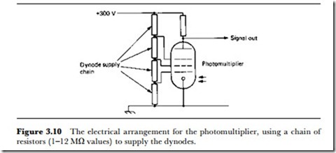
By cascading stages, this multiplication effect can be very large, so that, for example, five stages that each give a multiplication of 5 will increase the current of a beam from a photoemitter by a factor of 5 x 5 x 5 x 5 x 5 = 3125. This is unique among amplification methods in being virtually noiseless, and photomultipliers are used in detectors for very low light levels for specialized purposes. The secondary multiplying electrodes are known as dynodes, and each dynode must be run at a voltage level that is substantially greater than the one preceding it – Figure 3.10 shows a typical DC supply arrangement.
