Types of Power Unit
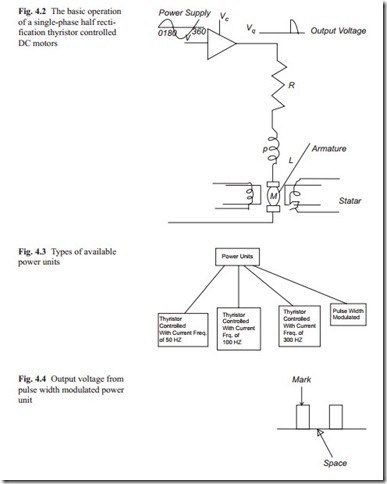
The recent development in power electronics is now possible to control large cur- rent with low power control signal. One of these devices is thyristor. The operation of a thyristor is similar to a transistor with an extra connection of a gate. When a low power level control signal is connected to the gate, large current flows through it and when the control signal is removed the conduction stops when the current be- comes zero. With this method, large DC servo motors can be controlled. For smaller motors, transistors are used to control the armature current. A simple diagram of thyristor controlled separately excited DC servo motor is shown in Fig. 4.2.
The power supply is connected to the input of the thyristor. The period of conduction depends on when the control signal Vc with respect to the position of input sine wave is excited. In this way, a portion of the sign wave will pass through the thyristor. The motor, because of rotor inertia, only responds to the average of output voltage. In Fig. 4.2, the armature resistance and inductance are shown by R and L. The output voltage is connected to the armature through brushes. The output volt- age although is rectified is a series of pulses. For half wave rectification, the output frequency is 50 Hz. When a full wave rectification is used, the output voltage frequency is 100 Hz. Single phase, two phase, and three phase half or full wave recti- fication produces output voltage 100, 200, and 300 Hz respectively. Of course, the higher the frequency of the output voltage, the smoother operation of the motors is achievable. The rotor fluctuation of speed will generate noise in sensors. Carefully designed velocity, position, and current transducers must be used various types of power supply for DC servo motors is shown in Fig. 4.3.
In the pulse width modulated (PWM) power unit, the power supply is first rectified with full wave rectification method. The DC conduction of the output voltage to the motor is controlled by transistors for smaller motors and with thyristor for larger motors. The output voltage will be a series of pulses with controlled mark to space ratio. This is shown in Fig. 4.4. With this method output, voltage of high
frequency is possible. A typical frequency may be as high as 2 kHz. This kind of frequency is often used for application where a high performance from the motor is required. In PWM power unit, transistors are used for smaller motors and thyristor are used for larger motors to control the voltage supplied to the motor. When thyristor is used, forcing circuits must be used to stop the conduction of thyristor because once triggered, it will continue to conduct until the current becomes zero.

