The 3-position Selector switch operators such as these can have mul- tiple contacts (see Fig. 2-13). It is recommended that this operator have a maximum of four 2 × 2 blocks. This can give it a total of 8 contacts, which can be Normally Open or Normally Closed. If more than this is needed, then you should consider using a relay. Typical use is for Hand/ Off/Auto operators. These operators can use the contacts in Fig. 2-3. For detailed specifications, see Allen Bradley at www.ab.com.
Line 1 The 3-position Selector switch is in the Hand position as indicated by the XOO, and the Stop button is closed. When the Start button is pressed, the motor starter will be energized and the M1 contact will close. The motor will run until the Stop button is depressed or the select switch position is changed.
Line 2 3-position Selector switch is in the Auto position as indicated by the OOX, and the float switch is closed. The motor will run until the liquid level drops and opens the float switch.
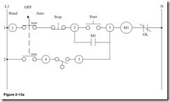
The 3-position keyed Selector switch operator in Fig. 2-13b can have multiple contacts. It is recommended that it have a maximum of four 2 × 2 blocks. This can give it a total of 8 contacts, which can be Normally Open or Normally Closed. If more than this is needed, then you should consider using a relay. Typical use is for Hand/Off/Auto operator. These operators can use the contacts in Fig. 2-3. For detailed specifications, see Allen Bradley at www.ab.com.
Shown in Fig. 2-13c:
Line 1 3-position keyed Selector is in the Hand position as indicated by the XOO, and the Stop button is closed. When the Start button is pressed, the motor starter will be energized and the M1 contact will close. The motor will run until the Stop button is depressed or the select switch position is changed.
Line 2 3-position keyed Selector is in the Auto position as indicated by the OOX, and the float switch is closed. The motor will run until the liquid level drops and opens the float switch.
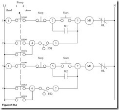
The 4-position Selector switch operators in Fig. 2-14 can have mul- tiple contacts. It is recommended that this operator have a maximum of four 2 × 2 blocks. This can give it a total of 8 contacts, which can be Normally Open or Normally Closed. If more than this is needed, then consider using a relay. Typical use is for Hand operation 1 operation 2 Auto operator. These operators can use the contacts in Fig. 2-3. For detailed specifications, see Allen Bradley at www.ab.com.
Shown in Fig. 2-14a:
Line 1 4-position Selector is in the Hand position as indicated by the XOOO, and the Stop button is closed. When the Start button is pressed, the motor starter will be energized, the M1 contact will close, and pump 1 will run until the Stop button is depressed or the select switch position is changed.
Line 2 4-position Selector is in the pump 1 or Auto position as indi- cated by the OXOO and the OOOX, and the float switch is closed. Pump 1 will run until the liquid level drops and opens the float switch.
Line 3 4-position Selector is in the Hand position as indicated by the XOOO, and the Stop button is closed. When the Start button is pressed, the motor starter will be energized, the M2 contact will close, and pump 2 will run until the Stop button is depressed or the select switch position is changed.
Line 4 4-position Selector is in the pump 2 or Auto position as indi- cated by the OOXO and the OOOX, and the float switch is closed. Pump 2 will run until the liquid level drops and opens the float switch.
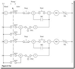
The 4-position keyed Selector switch operator in Fig. 2-15 can have mul- tiple contacts. It is recommended that it have a maximum of four 2 × 2 blocks. This can give it a total of 8 contacts, which can be Normally Open or Normally Closed. If more than this is needed, then you should con- sider using a relay. Typical use is for Hand operation 1 operation 2 Auto operator. These operators can use the contacts in Fig. 2-3. For detailed specifications, see Allen Bradley at www.ab.com.
Shown in Fig. 2-15a:
Line 1 4-position keyed Selector is in the Hand position as indicated by the XOOO, and the Stop button is closed. When the Start button is pressed, the motor starter will be energized, the M1 contact will close, and pump 1 will run until the Stop button is depressed or the select switch position is changed.
Line 2 4-position keyed Selector is in pump 1 or Auto position as indicated by the OXOO and the OOOX, and the float switch is closed. Pump 1 will run until the liquid level drops and opens the float switch.
Line 3 4-position keyed Selector is in the Hand position as indicated by the XOOO, and the Stop button is closed. When the Start button is pressed, the motor starter will be energized, the M2 contact will close, and pump 2 will run until the Stop button is depressed or the select switch position is changed.
Line 4 4-position keyed Selector is in pump 2 or Auto position as indicated by the OOXO and the OOOX, and the float switch is closed. Pump 2 will run until the liquid level drops and opens the float switch.
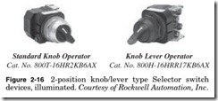
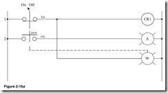
The 2-position illuminated Selector switch operators in Fig. 2-16 can be spring-return or maintained-position. This operator can have mul- tiple contacts; it is recommended that it have a maximum of four 2 × 2 blocks. This can give it a total of 8 contacts, which can be Normally Open or Normally Closed. If more than this is needed, then you should con- sider using a relay. Typical use is for On/Off operators. These operators can use the contacts in Fig. 2-3. For detailed specifications, see Allen Bradley at www.ab.com.
Shown in Fig. 2-16a:
Line 1 2-position Selector switch is in the On position as indicated by the XO; CR1 will be energized and the white pilot light will be on.
Line 2 2-position Selector switch is in the Off position as indicated by the OX; the amber pilot light will be on.
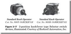
The 3-position lever illuminated Selector switch operators in Fig. 2- 17 can be spring-return or maintain-position. This operator can have multiple contacts. It is recommended that it have two blocks. This can give it a total of 4 contacts, which can be Normally Open or Normally Closed. If more than this is needed, then you should consider using a relay. Typical use is for Hand/Off/Auto operator. These operators can use the contacts in Fig. 2-3. For detailed specifications, see Allen Bradley at www.ab.com.
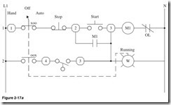
Shown in Fig. 2-17a:
Line 1 3-position keyed Selector is in the Hand position as indicated by the XOO, and the Stop button is closed. When the Start button is pressed, the motor starter will be energized, the M1 contact will close, and the motor will run until the Stop button is depressed or the select switch position is changed.
Line 2 3-position keyed Selector is in the Auto position as indicated by the OOX, and the float switch is closed. The motor will run and the white pilot light will be on until the liquid level drops and opens the float switch.
Note: A jumbo or large legend plate is recommended, if space allows.
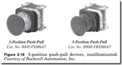
In the devices in Fig. 2-18, the center position is maintained. The top and bottom positions can be momentary or maintained. The button has one Normally Closed contact and one Normally Closed late break con- tact. For detailed specifications, see Allen Bradley at www.ab.com.
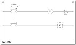
Shown in Fig. 2-18a:
Line 1 3-position push-pull device is in the Out position as indicated by the XOO; the motor starter will be energized, and the motor will run.
Line 2 3-position push-pull device is in the Out or center position as indicated by the XXO. The white pilot light will be on.
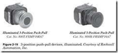
In the devices in Fig. 2-19, the center position is maintained. The top and bottom positions can be momentary or maintained. The button has one Normally Closed contact and one Normally Closed late break con- tact and has an internal pilot light. For detailed specifications, see Allen Bradley at www.ab.com.
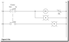
Shown in Fig. 2-19a:
Line 1 3-position push-pull device is in the Out position as indicated by the XOO. The motor starter will be energized, the motor will run, and the red pilot light will be on.
Line 2 3-position push-pull device is in the Out or center position as indicated by the XXO. The white pilot light will be on.
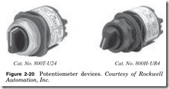
Potentiometers are used any time a variable resistance is needed (see Fig. 2-20). Caution should be taken to ensure that the potentiometer is not overloaded as this will cause damage. Typical use is to set the time delay of a relay. For detailed specifications, see Allen Bradley at www. ab.com.
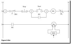
Shown in Fig. 2-20a:
Line 1 Terminal 1, then Normally Closed time contact from time delay relay TR1. The contact will open after a preset time when the TR1 is energized. Normally Closed Stop button, terminal 2 Normally Open Start button. Down one line, Normally Open M1 contact. Motor starter M1 with Normally Closed overload contact. When the Start button is pressed, then the M1 motor will be energized and the motor will run until the Stop button or the relay TR1 times out.
Line 2 Normally Open contact of motor starter M1. Time delay relay TR1 with adjustable time delay by use of the potentiometer. When the motor starter is energized, the contact M1 will close and start the time cycle set by the potentiometer.


![Figure 2-13c_thumb[1] Figure 2-13c_thumb[1]](http://machineryequipmentonline.com/electric-equipment/wp-content/uploads/2020/06/Figure-2-13c_thumb1_thumb.jpg)

