Input Devices part1
I define an input device as a device that by some action controls the output of an electrical circuit. As you can imagine, there are an unlimited number of input devices. I will try to cover the most common devices. There are many manufacturers of these devices. I will for the most part use Rockwell Automation’s Allen Bradley devices as I am most familiar with them and they are widely used in the field. The information contained here is not meant to replace the manufacturer’s specifications for detailed data; please see the manufacturer’s specifications.
Push Buttons and Selector Switches
The push button is a simple input device. The most basic is a single Normally Open contact. When the operator pushes the button, the cir- cuit will close and complete the circuit.
In Fig. 2-1 the push button controls a pilot.
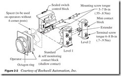
Figure 2-2 shows the breakdown of the 800T push button. The opera- tor can be any of the operators described in this chapter.
Most manufacturers use a modular design that allows you to use the same contacts for different types of operators. Allen Bradley has the following contact blocks available for their operators:
Shallow block
Small block used where the mounting has limited depth or the door swing is an issue. (See Fig. 2-3.)
PenTUFF (low-voltage) block
Used for hazardous locations; types 7 and 9 explosion proof (type 3 and type 4 ratings available with accessories). (See Fig. 2-3.)
Logic reed block
Sealed reed switch can be used in hazardous locations. 800T operators using logic reed contact blocks and installed in a suitable enclosure are UL listed as suitable for use in Class I, Division 2/Zone 2 hazardous locations. (See Fig. 2-3.)
Sealed switch block
Sealed contacts used for hazardous locations. 800T operators using sealed switch contact blocks and installed in a suitable enclosure are UL listed as suitable for use in Class I, Division 2/Zone 2 hazardous locations. (See Fig. 2-3.)
Stackable sealed switch block
Sealed contacts used for hazardous locations. 800T operators using sealed switch contact blocks and installed in a suitable enclosure are UL listed as suitable for use in Class I, Division 2/Zone 2 hazardous locations. (See Fig. 2-3.)
These contacts can be stacked up to the recommended two deep, a total of four blocks with the operator.
Not all the operators shown on the following pages can use all the contact types. (For detailed specifications, see Allen Bradley at www.ab.com.)
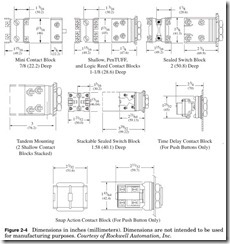
Dimensions for Allen Bradley 800T push buttons with contacts are shown in Fig. 2-4; these may change with different operators.
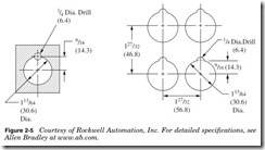
In Fig. 2-5 is shown the layout of the Allen Bradley 800T operators. This is the minimum distance between operators; your layout may be different.
Note: A jumbo or large legend plate is recommended, if space allows
The buttons in Fig. 2-6 are mechanically maintained. Typical use is for emergency stop or start, as in turning off all power in an IT Equipment Room (EPO) or starting the halon system in the event of a fire. For detailed specifications including a complete list of contacts, see Allen Bradley at www.ab.com.
When the push button in Fig. 2-6a is pressed, the relay CR1 loses power and the pilot light is energized.
Note: A jumbo or large legend plate is recommended, if space allows.
The buttons in Fig. 2-7 are mechanically maintained and illuminated. Typical use is for emergency stop or start, as in turning off all power in an IT Equipment Room (EPO) or starting the halon system in the event of a fire. For detailed specifications, see Allen Bradley at www.ab.com.
When the push button in Fig. 2-7a is pressed, the relay CR1 loses power and the pilot light is energized.
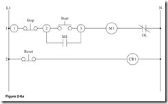
The push buttons in Fig. 2-8 can have multiple contacts. It is recom- mended that this push button have a maximum of four 2 × 2 blocks. This can give it a total of 8 contacts. If more than this is needed, then you should consider using a relay. These operators can use the contacts in Fig. 2-3. For detailed specifications, see Allen Bradley at www.ab.com.
Typically the Stop button will be an extended head unit red. The Start button will be a flush head unit green. The Reset button will be an extended head unit black.
Shown in Fig. 2-8a:
Line 1 The Stop button is closed. When the Start button is pressed, the M1 motor starter is energized and the M1 contact closes, and the motor starts and runs until the Stop button is pressed.
Line 2 When the Reset button is pressed, the relay CR1 loses power and resets something not shown.
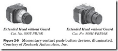
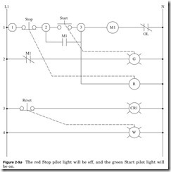
The illuminated push buttons in Fig. 2-9 can have two contact blocks. This can give it a total of 4 contacts. If more than this is needed, then you should consider using a relay. These operators can use the contacts in Fig. 2-3. For detailed specifications, see Allen Bradley at www.ab.com.
Shown in Fig. 2-9a:
Line 1 Stop button is closed. When the Start button is pressed, the M1 motor starter is energized, and the M1 contact closes, the red pilot light will be on, and the motor starts and runs until the Stop button is pressed.
Line 2 M1 contact will open and the green pilot light will be off.
Line 3 When the Reset button is pressed, the relay CR1 loses power and resets something not shown.
Line 4 White pilot light is on.
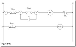
The push buttons in Fig. 2-10 have molded legends and can have multiple contacts. It is recommended that this push button have a maxi- mum of four 2 × 2 blocks. This can give a total of 8 contacts. If more than this is needed, then you should consider using a relay. These operators can use the contacts in Fig. 2-3. For detailed specifications, see Allen Bradley at www.ab.com.
Line 1 The Stop button is closed. When the Start button is pressed, the M1 motor starter is energized and the M1 contact closes, and the motor starts and runs until the Stop button is pressed.
Line 2 When the Reset button is pressed, the relay CR1 loses power and resets something not shown.
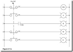
The 2-position Selector switch operators in Fig. 2-11 can have mul- tiple contacts. It is recommended that this operator have a maximum of four 2 × 2 blocks. This can give a total of 8 contacts, which can be Normally Open or Normally Closed. If more than this is needed, then you should consider using a relay. Typical use is for On/Off operators. These operators can use the contacts in Fig. 2-3. For detailed specifica- tions, see Allen Bradley at www.ab.com.
Shown in Fig. 2-11a:
Line 1 Selector switch is in the On position as indicated by the XO relay CR1 being energized.
Line 2 Selector switch is in the Off position as indicated by the OX relay; amber pilot light is energized.
Line 3 If relay CR1 is energized, then red pilot light is energized.
Line 4 Selector switch is in the On position as indicated by the XO relay; white pilot is energized.
Line 5 Selector switch is in the Off position as indicated by OX relay; green pilot light is energized.
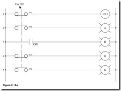
The 2-position keyed Selector switch operator in Fig. 2-12 can have multiple contacts. It is recommended that it have a maximum of four
2 × 2 blocks. This can give a total of 8 contacts, which can be Normally Open or Normally Closed. If more than this is needed, then you should consider using a relay. Typical use is for On/Off operators. These operators can use the contacts in Fig. 2-3. For detailed specifications, see Allen Bradley at www.ab.com.
Shown in Fig. 2-12a:
Line 1 Keyed Selector switch is in the On position as indicated by XO relay; CR1 is energized.
Line 2 Keyed Selector switch is in the Off position as indicated by OX relay; amber pilot light is energized.
Line 3 If relay CR1 is energized, then the red pilot light is energized.
Line 4 Keyed Selector switch is in the On position as indicated by XO relay; white pilot light is energized.
Line 5 Keyed Selector switch is in the Off position as indicated by OX relay; green pilot light is energized.
