CNC (COMPUTER NUMERICAL CONTROL) CONTROLLERS
CNC stands for computer numerical control, and refers specifically to the computer control of machine tools for repeatedly manufacturing complex parts. Many types of tools can have a CNC variant; lathes, milling machines, drills, grinding wheels, and so on. In an industrial production environment, all of these machines may be combined into one station to allow the continuous creation of a part.
CNC controllers are devices that control machines and processes. They range in capability from simple point-to-point linear control algorithms to highly complex nonlinear control algorithms that involve multiple axes and nonlinear movements. CNC controllers can be used to control various types of machine shop equipment, such as horizontal mills, vertical mills, lathes, turning centers, grinders, electro-discharge machines (EDM), welding machines, and inspection machines. The number of axes controlled by CNC controllers can range anywhere from one to five, with some CNC controllers configured to control more than six axes. Mounting types for CNC controllers include board, stand- alone, desktop, pendant, pedestal, and rack mount. Some units have integral displays, touch-screen displays, and keypads for controlling and programming.
The first benefit offered by all forms of CNC machine tools is improved automation. Operator intervention related to producing workpieces can be reduced or eliminated. Many CNC machines can run unattended during their entire machining cycle, freeing the operator to do other tasks. This results in reduced operator fatigue, fewer mistakes caused by human error, and consistent and predictable machining time for each workpiece. Since the machine will be running under program control, the skill level required by the CNC operator (related to basic machining practice) is also reduced compared with a machinist producing workpieces with conventional machine tools. The second major benefit of CNC technology is consistent and accurate workpieces. Today’s CNC machines boast almost unbe- lievable accuracy and repeatability specifications. This means that once a program is verified, two, ten, or one thousand identical workpieces can be easily produced with precision and consistency. A third benefit offered by most forms of CNC machine tools is flexibility. Since these machines are run from programs, changing to a different workpiece is almost as easy as loading a different program. Once a program has been verified and executed for one production run, it can be easily recalled the next time the workpiece is to be run. This leads to yet another benefit; fast changeover. These machines are very easy to set up and run, and since programs can be easily loaded, they allow very short setup time. This is imperative with today’s just-in-time production requirements.
CNC components and architectures
A computer numerical control (CNC) system consists of three basic components; CNC software, which is a program of instructions, a machine control unit, and processing equipment, also called the machine tool. The general relationship of these three components is illustrated in Figure 7.12.
(1) CNC software
Both the controller and the computer in CNC systems operate by means of software. There are three types of software programs required in either of them; operating system software, machine interface software, and application software.
The principal function of the operating system is to generate and handle the control signals which drive the machine tool axes. The machine tool interface software is used to operate the communication link between the central processing unit (CPU) and the machine tool axes to accomplish the control functions. Finally, in the application software, the program of instructions is the detailed step-by-step commands that direct the actions of the processing equipment. In machine tool applications, this program of instructions is called part programming. The individual command within the program refer to positions of a cutting tool relative to the worktable on which the work part is fixtured. Additional instructions are usually included, such as spindle speed, feed rate, cutting tool selection, and other. The program is coded in a suitable medium for submission to the machine control unit, called a controller.
(2) Machine control unit
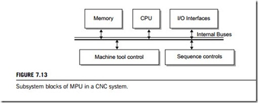
In today’s CNC technology, the machine control unit (MCU) consists of some type of computer with related control hardware that stores and sequentially executes the program of instructions by con- verting each command into mechanical actions of the processing equipment. The general configuration of the MCU in a CNC system is illustrated in Figure 7.13. A MCU generally consists of CPU, memory, I/O interfaces, controls of machine tool axes and spindle speed and sequence control for other machine tool functions. These subsystems are interconnected by means of an internal bus, as indicated in Figure 7.13.
The CPU, memory and I/O interfaces are described in Chapter 14 of this textbook. The MCU has two hardware subsystems machine tool controls and sequence controls which are different from normal computers. These components control the position and velocity (feed rate) of each machine axis as well as the rotational speed of the machine tool spindle. The control signals generated by the
MCU must be converted to a form and power level suited to those position control systems used to drive each machine. The positioning system can be classified as open-loop or closed-loop, and different hardware components are required in each case. The spindle is used to drive either the workpiece, as in turning, or a rotating cutter e.g. in milling and drilling. Spindle speed is a programmed parameter for most CNC machine tools, contolled by a drive control circuit and a feedback sensor interface. In addition to control of table position, feed rate, and spindle speed, several auxiliary functions, generally ON/OFF (binary) actuations, interlocks, and discrete numerical data are also controlled by the MCU.
(3) Machine tool/processing equipment
The processing equipment transforms the starting workpiece into a complete part. Its operation is directed by the MPU, which in turn is driven by instructions contained in the part program. In most CNC systems, the processing equipment consists of a worktable and spindle, as well as the motors and controls which drive them.
(4) Auxiliary and peripheral devices
Most CNC systems also contain some auxiliary devices such as; (1) field buses, (2) servo amplifiers, or(3) power supply devices. Peripherals may include: (1) keyboards, (2) graphic display interfaces such as monitors, (3) printers, and (4) disk drivers and tape readers. The microprocessor selected is bus oriented, and the peripherals can be connected to the bus via interface modules.
Computers, especially PCs are increasingly used in factories alongside typical CNC systems. Two configurations of computers and CNC controllers are:
1. Using a PC as a separate front-end interface for displaying the control process to operators, or for entering and encoding software programs into the controller. In this case, both the PC and the controller are interconnected by I/O interface modules; usually RS-232, RS-422, RS-485 or other RS-type interfaces.
2. The PC contains the motion control chips (or board) and the other hardware required to operate the machine tool. In this case, the CNC control chip fits into a standard slot of the PC, and the selected PC will require additional interface cards and programming.
In either configuration, the advantages of using a PC for CNC machining are its flexibility in executing a variety of software at the same time as controlling the machine tool. This may be programs for shop-floor control, statistical process control, solid modeling, cutting tool management, or other computer-aided manufacturing software. They are easy to use when compared with conventional CNC and can be networked. Possible disadvantages include losing time in retrofiting the PC for CNC, particularly when installing the controls inside the PC, and and also the PC may be a less efficient means of control. Advances in the technology of PC-based CNC are likely to reduce these disad- vantages over time.
CNC control mechanism
CNC is the process of “feeding” a set of sequenced instructions into a specially designed, program- mable controller and then using it to direct the movements of a machine tool such as a milling machine, lathe, or flame cutter. The program directs the cutter to follow a predetermined path at a specific spindle speed and feed rate, so resulting in the production of the desired geometric shape in a workpiece.
CNC controllers can operate in a number of modes, including polar coordinate command, cutter compensation, linear and circular interpolation, stored pitch error, helical interpolation, canned cycles, rigid tapping, and auto scaling. Polar coordinate command is a numerical control system in which all the coordinates are referred to a certain pole. Position is defined by the polar radius and polar angle with respect to this pole. Cutter compensation is the distance you want the CNC control to offset for the tool radius away from the programmed path. Linear and circular interpolation is the programmed path of the machine, which appears to be straight or curved, but is actually a series of very small steps along that path. Machine precision can be improved remarkably by stored pitch error compensation, which corrects for lead screw pitch error and other mechanical positioning errors. Helical interpolation is a technique used to make large-diameter holes in workpieces. It allows for high metal removal rates with a minimum of tool wear. There are machine routines such as drilling, deep drilling, reaming, tapping, boring, and so forth that involve a series of machine operations, but are specified by a single G-code with appropriate parameters. Rigid tapping is a CNC tapping feature where the tap is fed into the workpiece at the precise rate needed for a perfectly tapped hole. It also needs to retract at the same precise rate; otherwise it will shave the hole and create an out-of-specified tapped hole. Auto scaling translates the parameters of the CNC program to fit the workpiece.
Many other kinds of manufacturing equipment and manufacturing processes are controlled by other types of programmable CNC controllers. For example, a heat-treating furnace can be equipped with a controller that will monitor temperature and the furnace’s atmospheric oxygen, nitrogen, and carbon and make automatic changes to maintain these parameters within very narrow limits.
(1) CNC coordinate system
To program the CNC processing equipment, a standard axis system must be defined by which the position of the workhead relative to the workpart can be specified. There are two axis systems used in CNC, one for flat and prismatic workparts and the other for parts with rotational symmetry. Both axis systems are based on the Cartesian coordinate system.
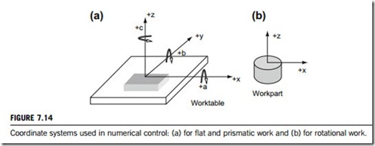
The axis system for flat and prismatic parts consists of three linear axes (x, y, z) in the Cartesian coordinate system, plus three rotational axes (a, b, c), as shown in Figure 7.14. In most machine tool
applications, the x- and y-axes are used to move and position the worktable to which the part is attached, and the z-axis is used to control the vertical position of the cutting tool. Such a positioning scheme is adequate for simple numerical control applications such as drilling and punching of flat sheet metal. Programming of these machine tools consists of little more than specifying a sequence of x y coordinates. The a-, b- , and c-rotational axes specify angular positions about the x-, y- and z-axes, respectively. To distinguish positive from negative angles, the right-hand rule is used. The rotational axes can be used for one or both of the following: (1) orientation of the workpart to present different surfaces for machining or (2) orientation of the tool or workhead at some angle relative to the part. These additional axes permit machining of complex workpart geometries. Machine tools with rota- tional axis capability generally have either four or five axes; the three linear axes, plus one or two rotational axes. Most CNC systems do not require all six axes.
The coordinate axes for a rotational numerical control system are illustrated in Figure 7.14(b). These systems are associated with numerical control lathes and turning centers. Although the work rotates, this is not one of the controlled axes on most of these turning machines. Consequently, the y-axis is not used. The path of a cutting tool relative to the rotating workpiece is defined in the x z plane, where the x-axis is the radial location of the tool, and the z-axis is parallel to the axis of rotation of the part.
The part programmer must decide where the origin of the coordinate axis system should be located, which is usually based on programming convenience. After this origin is located, the zero position is communicated to the machine tool operator for the cutting tool to be moved under manual control to some target point on the worktable, where the tool can be easily and accurately positioned.
(2) Motion control the heart of CNC
The most basic function of any CNC controller is automatic, precise, and consistent motion control. All forms of CNC equipment have two or more directions of motion, called axes. These axes determine precisely and automatically the position of the workpiece. The two most common axis types are as mentioned before, linear (driven along a straight path) and rotary (driven along a path that the workpiece rotates around).
Instead of causing motion by manually turning cranks and handwheels as is required on conven- tional machine tools, CNC machines allow motion to be actuated by servomotors under control of the CNC, and guided by the part program. All the parameters of the motion; the type (rapid, linear, and circular), the axes to move, the amount, and the rate (feed rate) are programmable with almost all CNC machine tools.
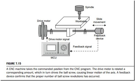
Figure 7.15 shows the makeup of a linear axis of a CNC controller. In this case, a command tells the drive motor to rotate a precise number of times. The rotation of the drive motor in turn rotates the ball screw, which drives the linear axis. A feedback device at the opposite end of the ball screw allows the control to confirm that the commanded number of rotations has taken place.
Although a rather crude analogy, the same basic linear motion can be found on a common table
vise. By rotating the vise crank, a lead-screw is rotated, which, in turn, drives the movable jaw on the vise. In comparison, a linear axis on a CNC machine tool is extremely precise. The number of revolutions of the axis drive motor precisely controls the amount of linear motion along the axis.
All discussions to this point have assumed that the absolute mode of programming is used, where the end points for all motions are specified from the program zero point. End points for axis motion can
also be specified by an incremental mode, in which end points for motions are specified from the tool’s current position, not from program zero. Although program zero point must be pinointed by one means or another, how this is done varies dramatically from one CNC controller to another. An older method is to assign program zero in the program. With this method, the programmer inputs the distance between the program zero and the starting position of the machine. A newer and better way to assign program zero is through some form of offset. Machining center control manufacturers commonly call offsets used to assign program zero fixture offsets. Turning center manufacturers commonly call offsets used to assign program zero for each tool geometry offsets.
Other motion types may exist in industrial applications, but the three most common types are available in almost all forms of CNC equipment, and are as follows:
(a) Rapid motion or positioning. This motion type is used to command motion at the machine’s fastest possible rate, used to minimize non-productive time during the machining cycle. Common uses include moving the tool to and from cutting positions, moving to clear clamps and other obstructions, and in general, any non-cutting motion during the program.
(b) Straight line motion. This allows the programmer to command a perfectly straight line and the motion rate (feed rate) to be used during the movement. Straight-line motion can be used whenever a straight cutting movement is required, including when drilling, turning a straight diameter, face or taper, and when milling straight surfaces. The method by which the feed rate is programmed varies from one machine type to the next, but in general, machining centers only allow the feed rate to be specific in per-minute format (inches or millimeters per minute). Turning centers also allow feed rate to be specified in per-revolution format (inches or millimeters per revolution).
(c) Circular motion. This motion type causes the machine to make movements in the form of a circular path, and is used to generate radii during machining. All feed-rate-related points for straight-line motion apply also to the circular motion.
(3) Interpolation
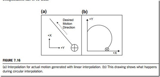
For perfectly straight movement, the x- and y-axis movements must themselves be perfectly synchronized, as given in Figure 7.16. Also, if machining is to occur during the motion, a motion rate (feed rate) must also be specified. This requires linear interpolation, where the control will precisely and automatically calculate a series of very tiny single axis departures, keeping the tool as close to the programmed linear path as possible. The machine tool appears to be forming a perfectly straight-line motion. Figure 7.16(a) shows what the CNC control is actually doing during linear interpolation.
In similar fashion, many applications for CNC machine tools require that the machine be able to form circular motions for instance, when forming radii on turned workpieces between faces and turns, and milling radii on contours on machining centers. This kind of motion requires circular interpolation. As with linear interpolation, the control will do its best to generate a path that is as close to that programmed as possible. Figure 7.16(b) shows what happens during circular interpolation.
Depending on the application, other interpolation types may be required on turning centers that have live tooling. For turning centers that can rotate tools (such as end mills) in the turret and have a c-axis to rotate the workpiece held in the chuck, polar coordinate interpolation can be used to mill contours around the periphery of the workpiece. This allows the programmer to “flatten out” the rotary axis, treating it as a linear axis for the purpose of making motion commands.
(4) Compensation
All types of CNC machine tools require compensation. Though applied for different reasons on different machine types, all forms of compensation are for unpredictable conditions related to tooling. In many applications, the CNC user will be faced with several situations when it will be impossible to predict exactly the result of certain tooling-related problems, hence one or another form of compensation has to be used.
(a) Tool length compensation
This type allows the programmer to ignore each tool length when the program is written. Instead of calculating z-axis positions based on the tool’s length, the programmer simply enters tool length compensation on each tool’s first z-axis approach movement to the workpiece.
During setup, the operator will input the tool length compensation value for each tool in the cor- responding offset. This, of course, means the tool must first be measured. If tool length compensation is used wisely, the tool can be measured offline (in a tool length measurement gauge) to minimize setup time. Figure 7.17 shows one popular method of determining the tool length compensation value. With this method, the value is simply the length of the tool.
(b) Cutter radius compensation
Just as tool length compensation allows tool length to be ignored, so cutter radius compensation allows the programmer to forget about the cutter’s radius when contours are programmed. It may be obvious that cutter radius compensation is only used for milling cutters, and only when milling on the periphery of the cutter. A programmer would never consider using cutter radius compensation for a drill, tap, reamer, or other hole-machining tool.
Without such compensation, the centerline path of all milling cutter must be entered into the program, and movements programmed according to the precise diameter of the milling cutter. This can be difficult enough with simple motions, but when contours become complicated, such calculation; become very difficult.
With cutter radius compensation, the programmer can use the coordinates of the work surface, not the tool’s centerline path, so eliminating the need for many calculations. It is worth mentioning that we are now talking about manual programming. If you have a computer-aided manufacturing (CAM) system, it can probably generate a centerline path just as easily as a work surface path.
(c) Dimensional tool offsets
This compensation type applies only to turning centers. Small errors are inevitable in the positioning of a tool when it is set up. In addition, single-point turning or boring tools will start to wear during use. Both these factors will directly affect the size of the workpiece being machined.
Dimensional tool offsets (also simply called tool offsets) are required to cope with these errors, and to allow easy sizing of turned workpieces. They are installed as part of a four-digit T word. The first two digits indicate the tool station number, and the second two digits indicate the offset number to be installed. When a tool offset is installed, the control actually shifts the entire coordinate system by the amount of the offset as if the operator could actually move the tool in the turret by the amount of the offset. Each dimensional offset has two values; one for the x- and one for the z-value. The operator will have control of what the tool does in both axes as the workpiece is being machined.
(d) Other types of compensation
The compensation types shown upto this point have been for machining and turning centers, but all forms of CNC equipment also have some form of compensation to allow for unpredictable situations. For instance, CNC wire EDM (electro-discharge machine) machines have two kinds of compensation; one, called wire offset, works in a very similar way to cutter radius compensation, and keeps the wire centerline away from the work surface by the length of wire radius plus the overturn amount. It is also used to help make trim (finishing) passes using the same coordinates.
Laser cutting machines also have a similar feature to cutter radius compensation to keep the radius of the laser beam away from the surface being machined. CNC press breaks compensate for bend allowances based on the workpiece material and thickness. Generally speaking, if the CNC user is faced with any unpredictable situations during programming, it is likely that the CNC control manufacturer has come up with a form of compensation to deal with the problem.
7.2.3 CNC part programming
CNC part programming consists of designing and documenting the sequence of processing steps to be performed on a CNC machine. To do this, a CNC programmer must be able to visualize the machining operations to be performed. Then, step-by-step, commands are issued to make the machine behave accordingly. Without good visualization, the programmer will not be able to develop the movements in the program correctly. Machinists frequently make the best CNC programmers since they can easily visualize any machining operation taking place.
(1) CNC program formats
The program format is the arrangement of the data that make up the program. Commands are fed to the controller, in units called blocks or statements. A block is one complete CNC instruction, and is made up of one or more commands, such as axis or feed rate commands. The format of command infor- mation within each block is very important. Five block formats are used in CNC programming:
(a) Fixed sequential format. This requires that specific command data items be organized together in a definite order to form a complete statement or block of information. Every block must have exactly the same number of characters (words). The significance of each character depends on where it is located in the block.
(b) Fixed sequential format with tab ignored. This is the same as above, except that tab codes are used to separate the characters for easier reading by humans.
(c) Tab sequential format. This is the same as the preceding format except that characters with the
same value as in the preceding block can be omitted in the sequence.
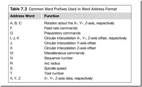
(d) Word address format. This format uses a letter prefix to identify the type of word that is a single alpha character. See Table 7.3 for definition of prefix. This features an address for each data element to permit the controller to assign data to their correct register in whatever order they are received. Almost all current CNC controllers use a word address format for programming.
(e) Word address format with tab separation and variable word order. This is the same as the last
format, except that characters are separated by tabs, and the characters in the block can be listed in any order.
Although the word address format allows variations in the order, the words in a block are usually given in the following order:
1. Sequence number (N-word).
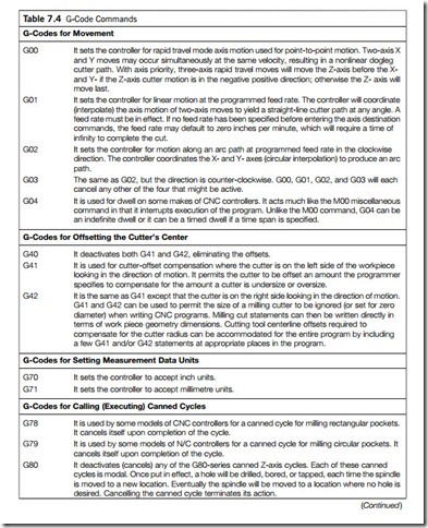
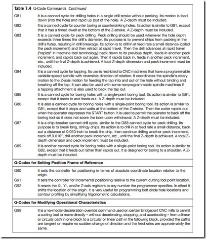
2. Preparatory word (G-word; see Table 7.4 for definition of G-word).
3. Coordinates (X-, Y-, Z-words for linear axes; A-, B-, C-axes for rotational axes).
4. Feed rate (F-word).
5. Spindle speed (S-word).
6. Tool selection (T-word).
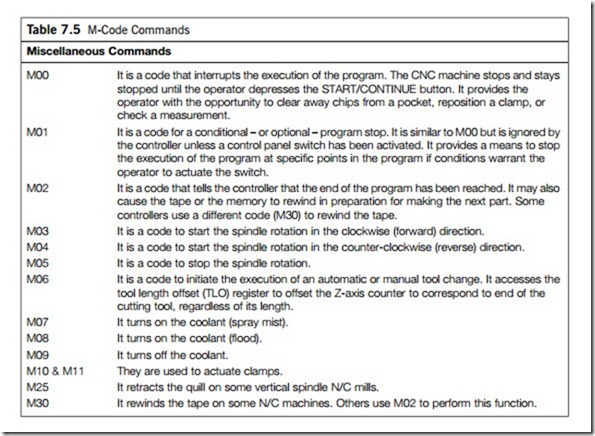
7. Miscellaneous word (M-word; see Table 7.5 for definition of M-word).
8. End-of-block (EOB symbol).
(2) Programming methodologies
Part programming can be accomplished using a variety of procedures ranging from highly manual to highly automated methods including (1) manual part programming, (2) computer-assisted part programming, and (3) conversational programming.
In manual part programming, the programmer prepares the CNC code using the low-level machine language previously described. The program is either written by hand on a form from which a punched tape or other storage medium is subsequently coded, or it is entered directly into a computer equipped with some CNC part programming software, which writes the program onto the storage medium. In either case, the manual part programming is a block-by-block listing of the machining instructions for the given job, formatted for a particular machine tool. Manual part programming can be used for both point-to-point and contouring jobs, but it is most suited to point-to-point machining operations, such as drilling. It can also be used for simple contouring jobs, such as milling and turning, when only two axes are involved. However, for complex three-dimensional machining operations, computer-assisted part programming are better.
Computer-assisted part programming systems, where the program is partially prepared auto- matically, allow CNC programming to be accomplished at a much higher level than manual part programming and are becoming very popular. The computer will generate the G-code level program and, once finished, the program will be transferred directly to the CNC machine tool. Whilst these systems vary dramatically from one system to the next, there are three basic steps that remain remarkably similar amongst them. First, the programmer must supply some general information.
290 CHAPTER 7 Industrial intelligent controllers
Second, workpiece geometry must be defined and trimmed to match the workpiece shape. Third, the machining operations must be defined. The first step requires documentation information such as part name, part number, date, program file name, and possibly graphic display size for scaling purposes. The workpiece material and rough stock shape may also be required. In the second step, the programmer will describe the shape of the workpiece by using a series of geometry definition methods, probably using graphic of each geometric element as it is described and selecting from a menu of definition methods, choosing the one that makes it the easiest to define the workpiece shape. Once geometry is defined, it will need to be trimmed to match the actual shape of the workpiece to be machined. Lines that run off the screen in both directions must be trimmed to form line segments. Circles must be trimmed to form radii. In the third step, the programmer tells the computer-assisted system how the workpiece is to be machined. Usually a tool path or animation will be shown, giving the programmer a very good idea of what will happen as the program is run. This ability to visualize a program before running it is a major advantage of graphic computer-assisted systems. Finally, the programmer can command that the G-code level CNC program be created.
With conversational programming, the program is created at the CNC machine, usually using
graphic and menu-driven functions. The various inputs can be checked as the program is created. When finished, most conversational controls will even show the programmer a tool path plot of what will happen during the machining cycle.
Conversational controls vary substantially from one manufacturer to the next. In most cases, they can essentially be thought of as a single-purpose computer-assisted system, and thus do provide a convenient means to generate part programs for a single machine. Some of these controls, partic- ularly older models, can only be programmed conversationally at the machine, which means other means such as offline programming with a computer-assisted system cannot be used. However, most new models can either operate in a conversational mode or accept externally generated G-code programs. Their uses is controversial, with some companies using them exclusively and swear by their use, whilst others consider them wasteful. Everyone involved with CNC seems to have a very strong opinion (pro or con) about them. Generally speaking, conversational controls can dramatically reduce the time it takes the operator to prepare the program when compared with manual part programming.
(3) CNC part programming languages
(a) G-code commands and M-commands require some elaboration. G-code commands are called preparatory commands, and consist of two numerical digits following the “G” prefix in the word address format; see Table 7.4 for details. M-code commands are used to specify miscellaneous or auxiliary functions, as explained in Table 7.5.
(b) Automatically programmed tools (APT) are a universal computer-assisted programming system for multiple-axis contouring programming. The original CNC programming system, developed for aerospace, was first used in building and manufacturing military equipment.
APT code is one of the most widely used software tools for complex numerically controlled machining. It is a “problem oriented” language, developed for the explicit purpose of driving CNC machine tools. Machine tool instructions and geometry definitions are written in the APT language to constitute a “part program”, which is processed by the APT software to produce a cutter location file. User-supplied post processors then convert the cutter location data into a form suitable for the particular CNC machine tool. The APT system software is organized into two separate programs; the load complex and the APT processor. The load complex handles the table initiation phase and is
FLC (fuzzy logic control) controllers 291
usually only run when changes to the APT processor capabilities are made. The APT processor consists of four components the translator, the execution complex, the subroutine library, and the cutter location editor. The translator examines each APT statement in the part program for recog- nizable structure and generates a new statement, or series of statements, in an intermediate language. The execution complex processes all of the definition, motion, and a related statement to generate cutter location coordinates. The subroutine library contains routines defining the algorithms required to process the sequenced list of intermediate language commands generated by the translator. The cutter location editor reprocesses the cutter location coordinates according to user-supplied commands to generate a final cutter location file.
The APT language is a statement oriented, sequence dependent language. With the exception of such programming techniques as looping and macros, statements in an APT program are executed in a strict first-to-last sequence. To provide programming capability for the broadest possible range of parts and machine tools, APT input (and output) is generalized, represented by three-dimensional geometry and tools, and is arbitrarily uniform, as represented by the moving tool concept and output data in absolute coordinates.

