Most modern industrial control systems are embedded networks, relying on built-in, special-purpose, digital or numerical controllers and computers to perform real-time and distributed control applications. They are used by controllers and computers to communicate with each other over dispersed locations, and to interact with large numbers of sensors and actuators.
Embedded networks are common in aircraft, factories, chemical processing plants, and also in machines such as cars. The types of architecture most commonly used are controller area, supervisory control and data acquisition, industrial Ethernet, DeviceNet, HART field, and industrial local area networks.
Their use raises many new practical and theoretical questions about network architecture, components, protocols, compatibility of operating systems, and ways to maximize the effectiveness of the embedded hardware. This part of the textbook provides students and engineers with a broad, comprehensive source of information and technological detail to enable them to address many questions and aspects of real-time and distributed control through use of embedded networks.
CONTROLLER AREA NETWORK (CAN)
Introduction
The controller area network (CAN) is a highly integrated system using serial bus and communications protocol to connect intelligent devices for real-time control applications. CAN is able to operate at data rates of up to 1 megabits per second over a possible line length of up to several kilometres, and has excellent error detection and confinement capabilities.
CAN was initially created by the German automotive system supplier Robert Bosch in 1985 as a working method for enabling robust serial communication. Since its inception, CAN has gained widespread popularity in industrial control and automation. In 1993, it became the international standard known as International Standard Organization (ISO) 11898. Since 1994, several higher-level protocols have been standardized on CAN, such as CANopen and DeviceNet. Thereafter, CAN has been documented in ISO 11898 (for high-speed applications) and ISO 11519 (for lower-speed applications).
CAN provides an inexpensive, durable network that helps multiple field devices communicate with one another. This allows electronic control units (ECU) to have a single CAN interface rather than separate analog and digital inputs for every device in the system. CAN was first created for automotive use, so its most common application is in vehicle electronic networking. However, as other industries have realized the advantages of CAN , it has been adopted for a wide variety of applications. Railway applications such as streetcars, trams, undergrounds, light railways, and long-distance trains incorporate CAN on different levels of the multiple networks within these vehicles. For example, CAN links the door units or brake controllers, passenger counting units, etc. CAN has also gained applications in aircraft for flight-state sensors, navigation systems, and research PCs in the cockpit. There are CAN buses in many aerospace applications, ranging from in-flight data analysis to aircraft engine control systems. Medical equipment uses CAN as an embedded network. In fact, hospital operating room components such as lights, tables, cameras, X-ray machines, and patient beds all have CAN-based systems. Lifts and escalators use embedded CAN networks, and hospitals use the CANopen protocol to link lifting devices, such as panels, controllers, doors, and light barriers, to each other and to control them. CANopen is also used in non-industrial applications such as laboratory equipment, sports cameras, telescopes, automatic doors, and even coffee machines.
CAN systems
Because it functions as a network and an interface, CAN has a bus with lines topology. The use of topology components is particularly advantageous in building automation systems to adapt the CAN bus flexibly to the requirements of line routing. Depending on the local network circumstances, CAN repeaters, CAN bridges, or gateways can be used.
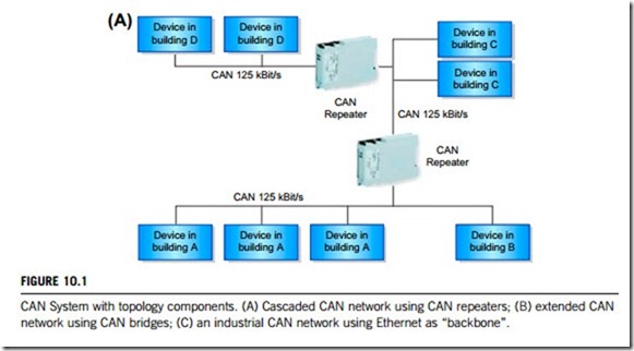
CAN networks integrate remote sensors or actuators with stub lines which can be implemented as CAN repeaters. As indicated in Figure 10.1(A), a network is physically separated through the use of CAN repeaters. The achievable stub lines length is only limited by the CAN baud rate used: this is only limited by the length between the two most distant devices in the complete CAN network. It is thus also possible to set up CAN systems in tree or star structures.
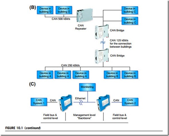
In Figure 10.1(B), CAN bridges divide a system into independent networks, so allowing networks with different baud rates to be connected to each other. Using an integrated filter function, messages can be filtered before transmission from one network to another in order to minimize the bus load on the individual networks. In contrast to CAN repeaters, CAN bridges allow the network
to be extended; by dividing it into several sub networks to increase the extension or the bus speed of the overall system: the effective line length of a CAN system can be increased by separating and interposing CAN bridges.
As shown in Figure 10.1(C), gateways are used to connect CAN networks to the same or other network types, for instance to connect management and service computers to CAN networks. Local CAN networks can also be connected via existing WAN/LAN (wide area network/local area network) connections with high transmission rates even with large extensions. It is thus possible to connect CAN networks via Ethernet over large distances with high data transmission rates.
In conclusion, by using topology components, CAN is ideally adapted to the requirements of line routing. Unnecessary cable looms are also avoided, planning, installation and operating costs are reduced, influences on the network due to faults from the outside are minimized and thus greater security is achieved.
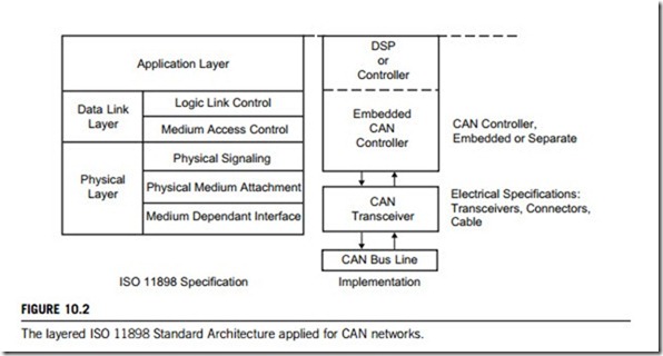
Fieldbus networks from the Open System Interconnection (OSI) network model point of view usually only implement layers 1, the physical layer, layer 2, the data-link layer, and layer 7, the
application layer. The intermediate layers are not needed because a Fieldbus network usually consists of a single network segment only (no need for transport and network layer, and has no notion of sessions or a need for different internal data presentation). Figure 10.2 displays the ISO 11898 standard architecture for CAN networks.
In the ISO 11898 standard architecture, there are three layers from top down: the application layer, the data-link layer, and the physical layer.
(1) Application layer
The application layer provides the high-level communication functions of the OSI layered model. These functions may be implemented by a system software developer or handled by a higher-layer protocol such as:
(a) CAL (CAN application layer)
CAL is based on an existing and proven protocol originally developed by Philips Medical Systems. CAL is an application-independent application layer that has been specified and is now maintained by the CAN in Automation (CiA) user group. CAL provides four application layer service elements:
1. CMS (CAN-based message specification): it offers objects of type variable, event and domain to design and specify how the functionality of a device (a node) can be accessed through its CAN interface exceeding the 8 bytes maximum data content of a CAN message, including an abort transfer feature. CMS derives from MMS (Manufacturing Message Specification), which is an application layer protocol designed for the remote control and monitoring of industrial devices.
2. NMT (network management): it offers services to support network management, e.g. to initialize, start or stop nodes, detect node failures; this service is implemented according to a master slave concept (there is one NMT master).
3. DBT (distributor): it offers a dynamic distribution of CAN identifiers (officially called Communication Object Identifier) to the nodes on the network; this service is implemented according to a master slave concept (there is one DBT master).
4. LMT (layer management): it offers the ability to change layer parameters to change the NMT
address of a node, or change the bit-timing and baud-rate of the CAN interface.
(b) CANopen
CAL provides all network management services and message protocols, but it does not define the contents of the CMS objects or the kind of objects being communicated. CANopen was developed to solve this problem. CANopen is built on top of CAL, using a subset of CAL services and commu- nication protocols; it provides an implementation of a distributed control system using the services and protocols of CAL. It does this in such a way that nodes can range from simple to complex in their functionality without compromising interoperability between the nodes in the network.
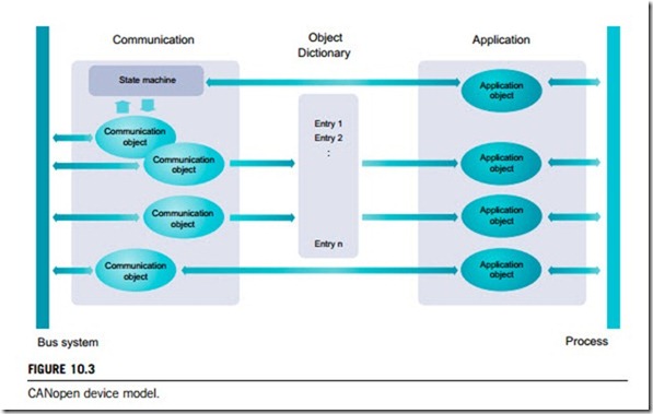
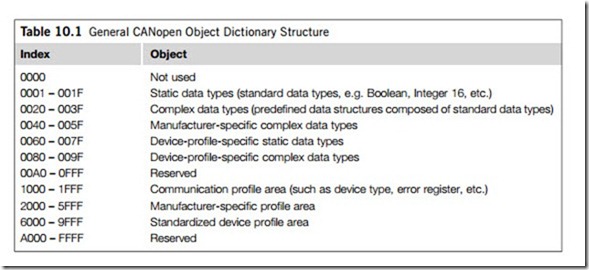
The central concept in CANopen is the device object dictionary (OD), a concept also used in other Fieldbus systems (Profibus, Interbus-S). Every node in the network is assigned an OD containing all parameters that describe the device and its network behavior. The CANopen object dictionary (OD) is an ordered grouping of objects; each object is addressed using a 16-bit index. To allow individual elements within data structures to be accessed, an 8-bit sub-index has been defined as well. The CANopen device model with OD is displayed in Figure 10.3 and the general layout of the CANopen OD is shown in Table 10.1.
DeviceNet uses the CAN standard as the foundation for a higher-level communication protocol, so is often referred to as a CAN application layer protocol. The DeviceNet specification determines the way data are organized and transferred between devices as an object model that devices need to implement. This ensures that all devices present a consistent interface to the rest of the network, hiding their internal details. DeviceNet networks will be the topic of section 10.4 of this chapter; only the linkage between the CAN application layer and the DeviceNet application layer is briefly mentioned here.
(2) Data-link layer
The data-link layer is responsible for transferring messages (or frame) from a given node to all other nodes in the CAN network. This layer handles bit stuffing and checksums for error handling, and after sending a message, waits for acknowledgment from the receivers. It is subdivided into two further layers:
(a) the logical link control layer (LLC), which accepts messages by a filtering process; overload notification and recovery management tasks will be taken care of by this layer;
(b) the medium access control layer (MAC), which carries out data encapsulation, frame coding
and arbitration, media access management, error detection and signaling and acknowledgment tasks.
(3) Physical layer
The data-link and physical layers of Figure 10.2, which are normally transparent to a system operator, are included in any controller that implements the CAN protocol with integrated CAN controller. This layer implements: physical signalling, which includes bit encoding and decoding, bit transmit timing and synchronization; identifying the driver and receiver characteristics attached to the CAN bus; and interfacing with connectors.
CAN has several different physical layers which classify certain aspects of the network. The most widely used are described below:
(a) High-speed CAN
High-speed CAN is the most common physical layer. Networks are implemented with two wires and allow communication at transfer rates up to 1 Mb/s. It is also known as CAN C and ISO 11898-2. Typical high-speed CAN devices include anti-lock brake systems, engine control modules, and emissions systems.
(b) Low-speed/fault-tolerant CAN hardware
Low-speed/fault-tolerant CAN networks are also implemented with two wires, they can communicate with devices at rates up to 125 kb/s, and offer transceivers with fault-tolerant capabilities. Other names for low-speed/fault-tolerant CAN include CAN-B and ISO 11898-3. Typical low-speed, fault-tolerant devices in an automobile include comfort devices. Wires that have to pass through the door of a vehicle are low-speed, fault-tolerant to cope with the stress that is imposed when opening and closing a door. Also, in situations where an advanced level of security is desired, such as with brake lights, low-speed, fault-tolerant CAN offers a solution.
(c) Single-wire CAN hardware
Single-wire CAN interfaces can communicate at rates up to 33.3 kb/s (88.3 kb/s in high-speed mode). These interfaces are also known as SAE-J2411, CAN A, and GMLAN. Typical single-wire devices within an automobile are those that do not require high performance, such as seat and mirror adjusters.
(d) Software-selectable CAN hardware
Software-selectable CAN interfaces can often be configured to use any of the onboard transceivers (high-speed, low-speed, fault-tolerant, or single-wire CAN). Multiple-transceiver hardware offers the perfect solution for applications that require a combination of different communications standards. Software-selectable CAN hardware can choose the appropriate external CAN transceiver.
CAN communication
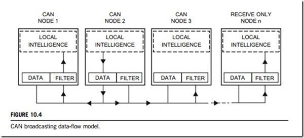
CAN communication is a broadcast mechanism. A transmitting node places data on the network for all nodes to access (Figure 10.4). However, only those nodes requiring updated data allow the data message to pass through a filter. If this filter is not set, much of a node’s microprocessing time is spent sorting through messages that are not needed.
(1) CSMA/CD protocol
The CAN communication protocol is a CSMA/CD protocol. CSMA stands for carrier sense multiple access, which means that every node on the network must monitor the bus for a period of no activity before trying to send a message on that bus (carrier sense). Also, once this period of no activity occurs, every node on the bus has an equal opportunity to transmit a message (multiple access). The CD stands for collision detection. If two nodes on the network start transmitting at the same time, the nodes will detect the collision and take the appropriate action. In CAN protocol, a non-destructive bitwise arbitration method is utilized, so messages remain in action after arbitration is completed even if
collisions are detected. All of this arbitration takes place without corruption or delay of the higher- priority message. To support non-destructive bitwise arbitration, logic states need to be defined as dominant or recessive. The transmitting node must also monitor the state of the bus to see whether the logic state it is trying to send actually appears on the bus.
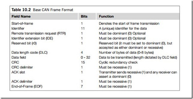
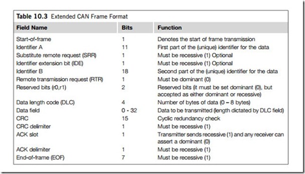
The CAN protocol defines 0 as a dominant bit, and 1 as a recessive bit. A dominant bit state will always be preferred arbitration over a recessive state, therefore the lower the value is in the message identifier (the field used in the message arbitration process; see Tables 10.2 and 10.3), the higher the priority of the message will be. As an example, suppose two nodes are trying to transmit a message at the same time. Each node will monitor the bus to make sure the bit that it is trying to send actually
appears on the bus. The lower-priority message will at some point try to send a recessive bit and the monitored state on the bus will be dominant. At that point this node loses arbitration and immediately stops transmitting. The higher-priority message will continue to completion, and the losing node will wait for the next period of no activity on the bus to attempt transmission again.
(2) Message-based communication
The CAN protocol is a message-based protocol, rather than an address-based protocol. This means that messages are not transmitted from one node to another node on an address basis. CAN messages comprise the priority and the contents of the data being transmitted. All nodes in the system receive every message transmitted on the bus, and will acknowledge if the message was properly received (Figure 10.4). Each node needs to decide whether the message received should be immediately discarded or kept to be processed. A single message can be destined for one node, or many nodes. A node can also request information from other nodes. This is called a remote transmit request (RTR) node that specifically requests data to be sent to it rather than passively waiting to receive information.
Two examples are given in this paragraph to show how CAN performs message-based commu- nication. Firstly, an automotive airbag sensor is connected via CAN to a safety system router node only. This router node takes in other safety system information and routes it to all other nodes on the safety system network. All the other nodes on the safety system network can then receive the latest airbag sensor information from the router at the same time, acknowledge if the message was received properly, and decide whether to utilize this information or discard it. The second example is a safety system in a car that gets frequent updates from critical sensors such as the airbags, but does not receive frequent updates from other sensors (such as the oil pressure sensor or the low battery sensor) to make sure they are functioning properly. It can request data periodically from these other sensors and perform a thorough safety system check. The system designer can utilize this feature to minimize network traffic while still maintaining the integrity of the network.
One additional benefit of this message-based protocol is that additional nodes can be added to the system without the necessity to reprogram all other nodes to recognize the addition. The new node will start receiving messages from the network and, based on the message ID, decide whether to process or discard the received information.
The CAN protocol defines four different types of messages (or frames). The first and most common is a data frame, used when a node transmits information to any or all other nodes in the system. Second is a remote frame, a data frame with the RTR bit set so as to signify that it is a remote transmit request. The other two frame types error frames and overload frames are used for error handling. Error frames are generated by nodes that detect any of the protocol errors defined by CAN. Overload errors are generated by nodes that require more time to process messages already received. Table 10.2 is the Base CAN frame format. Table 10.3 is the Extended CAN frame format.
(3) Error handling
CAN nodes can determine fault conditions and change to different modes based on the severity of the problems encountered. They also have the ability to distinguish short disturbances from permanent failures and modify their functionality accordingly. CAN nodes can change from functioning like a normal node (being able to transmit and receive messages normally), to shutting down completely (bus-off) based on the severity of the errors detected. This feature is called fault confinement. No faulty CAN node or nodes will be able to monopolize all of the bandwidth on the network because faults will be confined to the faulty nodes, which will shut off, so preventing network failure. This is very powerful because fault confinement guarantees bandwidth for critical system information.
There are five error conditions that are defined in the CAN protocol and three error states that a node can exist in, based upon the type and number of error conditions detected. The following describes each in more detail.
(a) Error conditions
1. CRC error. A 15-bit cyclic redundancy check (CRC) value is calculated by the transmitting node and transmitted in the CRC field. All nodes on the network receive this message, calculate a CRC and verify that the CRC values match. If the values do not match, a CRC error occurs and an error frame is generated. Since at least one node did not properly receive the message, it is then resent after a proper intermission time.
2. Acknowledge error. In the acknowledge field of a message, the transmitting node checks whether the acknowledge slot (which it has sent as a recessive bit) contains a dominant bit. This dominant bit would acknowledge that at least one node correctly received the message. If this bit is recessive, then no node received the message properly, and an acknowledge error has occurred. An error frame is then generated and the original message will be repeated after a proper intermission time.
3. Form error. If any node detects a dominant bit in one of the following four segments of the message: end of frame, interframe space, acknowledge delimiter or CRC delimiter, the CAN protocol defines this as a form violation and a form error is generated. The original message is then resent after a proper intermission time. (Please see Table 10.2 and/or Table 10.3 for where these segments lie in a CAN message.)
4. Bit error. A bit error occurs if a transmitter sends a dominant bit and detects a recessive bit, or if it sends a recessive bit and detects a dominant bit when monitoring the actual bus level and comparing it to the bit that it has just sent. In the case where the transmitter sends a recessive bit and a dominant bit is detected during the arbitration field or acknowledge slot, no bit error is generated because normal arbitration or acknowledgment is occurring. If a bit error is detected, an error frame is generated and the original message is resent after a proper intermission time.
5. Stuff error. CAN protocol uses a non-return-to-zero (NRZ) transmission method. This means that the bit level is placed on the bus for the entire bit time. CAN is also asynchronous, and bit stuffing is used to allow receiving nodes to synchronize by recovering clock information from the data stream. Receiving nodes synchronize on recessive to dominant transitions. If there are more than five bits of the same polarity in a row, CAN issues automatically stuff an opposite polarity bit in the data stream. The receiving node(s) will use it for synchronization, but will ignore the stuff bit for data purposes. If, between the start of frame and the CRC delimiter, six consecutive bits with the same polarity are detected, then the bit stuffing rule has been violated. A stuff error then occurs, an error frame is sent, and the message is repeated.
(b) Error states
Detected errors are made public to all other nodes via error frames or error flags. The transmission of an erroneous message is aborted and the frame is repeated as soon as the message can again win arbitration on the network. Each node will be in one of three error states at this point; error-active, error-passive or bus-off.
1. Error-active. An error-active node can actively take part in bus communication, including sending
an active error flag (which consists of six consecutive dominant bits). The error flag actively violates the bit stuffing rule and causes all other nodes to send an error flag, called the error echo flag, in response. An active error flag and the subsequent error echo flag may cause as many as twelve con- secutive dominant bits on the bus; six from the active error flag, and zero to six more from the error echo flag depending upon when each node detects an error on the bus. A node is error-active when both the transmit error counter (TEC) and the receive error counter (REC) are below 128. Error-active is the normal operational mode, allowing the node to transmit and receive without restrictions.
2. Error-passive. A node becomes error-passive when either the transmit error counter or receive error counter exceeds 127. Error-passive nodes are not permitted to transmit active error flags on the bus, but instead, transmit passive error flags which consist of six recessive bits. If the error-passive node is currently the only transmitter on the bus then the passive error flag will violate the bit stuffing rule and the receiving node(s) will respond with error flags of their own (either active or passive depending upon their own error state). If the error-passive node in question is not the only transmitter (i.e. during arbitration) or is a receiver, then the passive error flag will have no effect on the bus due to the recessive nature of the error flag. When an error-passive node transmits a passive error flag and detects a dominant bit, it must see the bus as being idle for eight additional bit times after an intermission before recognizing the bus as available. After this time, it will attempt to retransmit.
3. Bus-off. A node goes into the bus-off state when the transmit error counter is greater than 255 (receive errors cannot cause a node to go bus-off). In this mode, the node cannot send or receive messages, acknowledge messages, or transmit error frames of any kind. This is how fault confinement is achieved. There is a bus recovery sequence defined by the CAN protocol that allows a node that is bus-off to recover, return to error-active, and begin transmitting again if the fault condition is removed.
CAN bus
The CAN bus is a multiplexed wiring system used to connect the ECU as nodes to the CAN network.
(1) CAN bus I/O interface
The CAN standard defines a communication network that links all the nodes connected to a bus and enables them to communicate with one another. There may or may not be a central control node, and nodes may be added at any time, even while the network is operating (hot-plugging). All the nodes are connected to the network by interface devices that can be CAN transceivers or CAN connectors. These interface devices commonly have the following parameters specified: supply voltage; high short- circuit protection; bus-input impedance; wide common-mode range; thermal shutdown protection; low current standby and sleep mode; controlled transition time; etc.
(2) Bus length and signaling rate
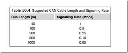
The basics of arbitration require that the front wave of the first bit of a CAN message should travel to the most remote node on a CAN network and back again before the bit is designated by the receiver of the sending node as dominant or recessive (typically this sample is made at about two-thirds the bit width). With this limitation, the maximum bus length and signaling rate are determined by network parameters. Factors to be considered in network design include the (approximately) 5 ns/m propa- gation delay of a typical twisted-pair bus cable, signal amplitude loss due to the loss mechanisms of the cable, and the input impedance of the bus transceivers. Under strict analysis, variations among the different oscillators in a system also need to be accounted for by adjustments in signaling rate and bus length. Maximum signaling rates achieved with the SN65HVD230 in high-speed mode with several bus lengths are listed in Table 10.4.
(3) Maximum number of nodes
In practice, up to 64 nodes may be connected to a DeviceNet bus, 127 on a CANopen bus and up to 255 nodes may be connected together on a CAN bus. When more than the standard 30 nodes are used on a bus, it is recommended that a transceiver (or connector) with high bus-input impedance be used.
A problem may develop when too many transceivers (or connectors) source or sink current from or onto the bus. When a device begins to transmit a message, it has to sink or source all of the leakage current on the bus, plus drive the standard signal voltage levels across the termination resistance. If the current demand is too great, the device may be driven into thermal shut-down or even destroyed.
To prevent transceiver (or connector) damage, the voltage difference between reference grounds of the nodes on a bus should be held to a minimum. This is the common-mode voltage across the entire system and although many transceivers (or connectors) are designed to operate over an extended common-mode range, the cumulative current demand of too many devices at a common-mode voltage extreme may jeopardize network security. To enhance this common-mode security, higher-layer protocols such as DeviceNet specify that power and ground wires be carried along with the signaling pair of wires. Several cable companies have developed four-wire bundled cables specifically for these applications.
