4.1. INTRODUCTION
As shown in Chapter 2, the slots of the stator and rotor cores of induction machines are filled with electric conductors, insulated (in the stator) from cores, and connected in a certain way. This ensemble constitutes the windings. The primary (or the stator) slots contain a polyphase (triple phase or double phase) a.c. winding. The rotor may have either a 3(2) phase winding or a squirrel cage. Here we will discuss the polyphase windings.
Designing a.c. windings means, in fact, assigning coils in the slots to various phases, establishing the direction of currents in coil sides and coil connections per phase and between phases, and finally calculating the number of turns for various coils and the conductor sizing.
We start with single pole number three-phase windings as they are most commonly used in induction motors. Then pole changing windings are treated in some detail. Such windings are used in wind generators or in doubly fed variable speed configurations. Two phase windings are given special attention. Finally, squirrel cage winding m.m.fs are analyzed.
Keeping in mind that a.c. windings are a complex subject having books dedicated to it [1,2] we will treat here first its basics. Then we introduce new topics such as “pole amplitude modulation,” ”polyphase symmetrization” [4], “intersperse windings” [5], “simulated annealing” [7], and “the three-equation principle” [6] for pole changing. These are new ways to produce a.c. windings for special applications (for pole changing or m.m.f. chosen harmonics elimination). Finally, fractional multilayer three-phase windings with reduced harmonics content are treated in some detail [8,9]. The present chapter is structured to cover both the theory and case studies of a.c. winding design, classifications, and magnetomotive force (mmf) harmonic analysis.
4.2. THE IDEAL TRAVELING M.M.F. OF A.C. WINDINGS
The primary (a.c. fed) winding is formed by interconnecting various conductors in slots around the circumferential periphery of the machine. As shown in Chapter 2, we may have a polyphase winding on the so-called wound rotor. Otherwise, the rotor may have a squirrel cage in its slots. The objective with polyphase a.c. windings is to produce a pure traveling m.m.f., through proper feeding of various phases with sinusoidal symmetrical currents. And all this in order to produce constant (rippleless) torque under steady state:
Fs1(x,t) = Fs1m cosπτ x − ω1t − θ0 (4.1) where
x – coordinate along stator bore periphery τ – spatial half-period of m.m.f. ideal wave ω1 – angular frequency of phase currents θ0 – angular position at t = 0
We may decompose (4.1) into two terms
Fs1(x,t) = Fs1m cosπτ x − θ0 cosω1t + sinπτ x − θ0 sinω1t (4.2)
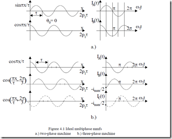
Equation (4.2) has a special physical meaning. In essence, there are now two mmfs at standstill (fixed) with sinusoidal spatial distribution and sinusoidal currents. The space angle lag and the time angle between the two mmfs is π/2. This suggests that a pure traveling mmf may be produced with two symmetrical windings π/2 shifted in time (Figure 41.a). This is how the two phase induction machine evolved.
Similarly, we may decompose (4.1) into 3 terms
Fs1(x,t) = 23 Fs1m cosπτ x − θ0 cosω1t + cosπτ x − θ −0 23πcosω1t −23π +
+ cosπτ x − θ +0 23π cosω1t + 23π
(4.3)
Consequently, three mmfs (single-phase windings) at standstill (fixed) with sinusoidal spatial (x) distribution and departured in space by 2π/m radians, with sinusoidal symmetrical currents−equal amplitude, 2π/3 radians time lag angle−are also able to produce also a traveling mmf (Figure 4.1.b).
In general, m phases with a phase lag (in time and space) of 2π/3 can produce a traveling wave. Six phases (m = 6) would be a rather practical case besides m = 3 phases. The number of mmf electrical periods per one revolution is called the number of pole pairs p1
πD ; 2p1 = 2,4,6,8,… (4.4)
p1 = 2τ where D is the stator bore diameter.
It should be noted that, for p1> 1, according to (4.4), the electrical angle αe is p1 times larger than the mechanical angle αg
α =e p1αg (4.5)
A sinusoidal distribution of mmfs (ampereturns) would be feasible only with the slotless machine and windings placed in the airgap. Such a solution is hardly practical for induction machines because the magnetization of a large total airgap would mean very large magnetization mmf and, consequently, low power factor and efficiency. It would also mean problems with severe mechanical stress acting directly on the electrical conductors of the windings.
Figure 4.1 Ideal multiphase mmfs
a.) two-phase machine b.) three-phase machine
In practical induction machines, the coils of the windings are always placed in slots of various shapes (Chapter 2).
The total number of slots per stator Ns should be divisible by the number of phases m so that
N / ms = integer (4.6)
A parameter of great importance is the number of slots per pole per phase q: q = Ns (4.7)
2p m1
The number q may be an integer (q = 1,2, … 12) or a fraction.
In most induction machines, q is an integer to provide complete (pole to pole) symmetry for the winding.
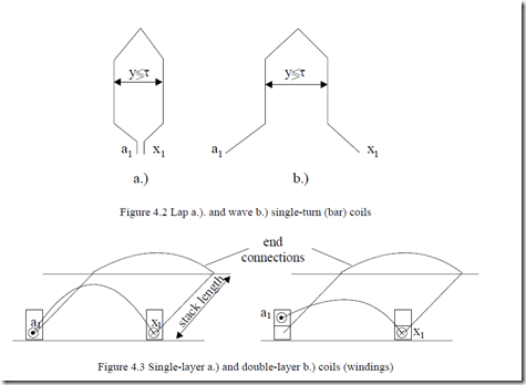
The windings are made of coils. Lap and wave coils are used for induction machines (Figure 4.2).
The coils may be placed in slots in one layer (Figure 4.2a) or in two layers (Figure 4.3.b).
Single layer windings imply full pitch (y = τ) coils to produce an mmf fundamental with pole pitch τ.
Double layer windings also allow chorded (or fractional pitch) coils (y <τ) such that the end connections of coils are shortened and thus copper loss is reduced. Moreover, as shown later in this chapter, the harmonics content of mmf may be reduced by chorded coils. Unfortunately, so is the fundamental.
4.3. A PRIMITIVE SINGLE-LAYER WINDING
Let us design a four pole (2p1 = 4) three-phase single-layer winding with q = 1 slots/pole/phase. Ns = 2p1qm = 2·2·1·3 = 12 slots in all.
From the previous paragraph, we infer that for each phase we have to produce an mmf with 2p1 = 4 poles (semiperiods). To do so, for a single layer winding, the coil pitch y = τ = Ns/2p1 = 12/4 = 3 slot pitches.
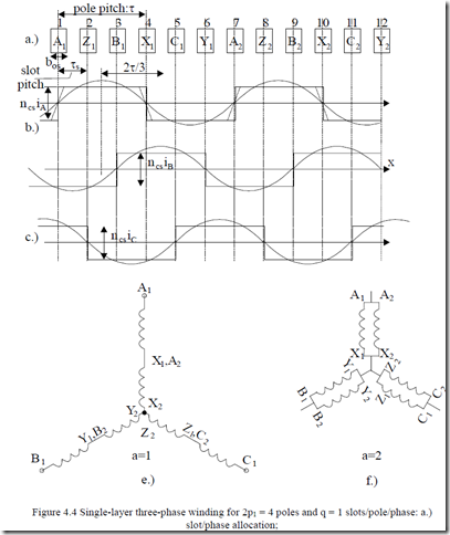
For 12 slots there are 6 coils in all. That is, two coils per phase to produce 4 poles. It is now obvious that the 4 phase A slots are y = τ = 3 slot pitches apart. We may start in slot 1 and continue with slots 4, 7, and 10 for phase A (Figure 4.4a).
Phases B and C are placed in slots by moving 2/3 of a pole (2 slots pitches in our case) to the right. All coils/phases may be connected in series to form one current path (a = 1) or they may be connected in parallel to form two current
paths in parallel (a = 2). The number of current paths a is obtained in general by connecting part of coils in series and then the current paths in parallel such that all the current paths are symmetric. Current paths in parallel serve to reduce wire gauge (for given output phase current) and, as shown later, to reduce uncompensated magnetic pull between rotor and stator in presence of rotor eccentricity.
b.), c.), d.) ideal mmf distribution for the three phases when their currents are maximum;
e.) star series connection of coils/phase; f.) parallel connection of coils/phase
If the slot is considered infinitely thin (or the slot opening bos≈ 0), the mmf
(ampereturns) jumps, as expected, by ncs⋅iA,B,C, along the middle of each slot.
For the time being, let us consider bos = 0 (a virtual closed slot).
The rectangular mmf distribution may be decomposed into harmonics for each phase. For phase A we simply obtain
FA1 ![]() x,t x (4.8) For the fundamental, ν = 1, we obtain the maximum amplitude. The higher the order of the harmonic, the lower its amplitude in (4.8).
x,t x (4.8) For the fundamental, ν = 1, we obtain the maximum amplitude. The higher the order of the harmonic, the lower its amplitude in (4.8).
While in principle such a primitive machine works, the harmonics content is too rich.
It is only intuitive that if the number of steps in the rectangular ideal distribution would be increased, the harmonics content would be reduced. This goal could be met by increasing q or (and) via chording the coils in a two-layer winding. Let us then present such a case.
4.4. A PRIMITIVE TWO-LAYER CHORDED WINDING
Let us still consider 2p1 = 4 poles, m = 3 phases, but increase q from 1 to 2. Thus the total number of slots Ns = 2p1qm = 2·2·2·3 = 24.
The pole pitch τ measured in slot pitches is τ = Ns/2p1 = 24/4 = 6. Let us reduce the coil throw (span) y such that y = 5τ/6.
We still have to produce 4 poles. Let us proceed as in the previous paragraph but only for one layer, disregarding the coil throw.
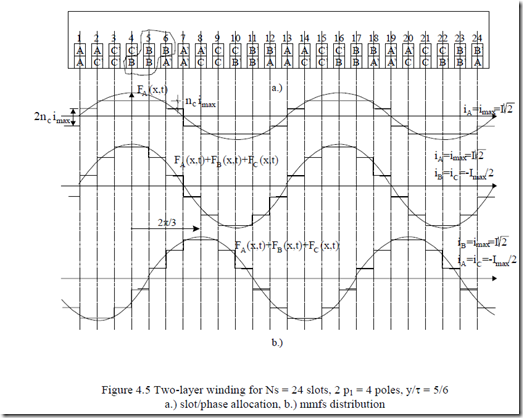
In a two, layer winding, the total number of coils is equal to the number of slots. So in our case there are Ns/m = 24/3 coils per phase. Also, there are 8 slots occupied by one phase in each layer, four with inward and four with outward current direction. With each layer each phase has to produce four poles in our case. So slots 1, 2; 7’, 8’; 13, 14; 19’, 20’ in layer one belong to phase A. The superscript prime refers to outward current direction in the coils. The distance between neighbouring slot groups of each phase in one layer is always equal to the pole pitch to preserve the mmf distribution half-period (Figure 4.5). Notice that in Figure 4.5, for each phase, the second layer is displaced to the left by τ-y = 6-5 = 1 slot pitch with respect to the first layer. Also, after two poles, the situation repeats itself. This is typical for a fully symmetrical winding. Each coil has one side in one layer, say, in slot 1, and the second one in slot y + 1 = 5 + 1 = 6. In this case all coils are identical and thus the end connections occupy less axial room and are shorter due to chording. Such a winding is typical with random wound coils made of round magnetic wire.
For this case we explore the mmf ideal resultant distribution for the situation when the current in phase A is maximum (iA = imax). For symmetrical currents, iB = iC = −imax/2 (Figure 4.1b).
Each coil has nc conductors and, again with zero slot opening, the mmf jumps at every slot location by the total number of ampereturns. Notice that half the slots have coils of same phase while the other half accommodate coils of different phases.
The mmf of phase A, for maximum current value (Figure 4.5b) has two steps per polarity as q = 2. It had only one step for q = 1 (Figure 4.4). Also, the resultant mmf has three unequal steps per polarity (q + τ-y = 2 + 6-5 = 3). It is indeed closer to a sinusoidal distribution. Increasing q and using chorded coils reduces the harmonics content of the mmf.
Also shown in Figure 4.5 is the movement by 2τ/3 (or 2π/3 electrical radians) of the mmf maximum when the time advances with 2π/3 electrical (time) radians or T/3 (T is the time period of sinusoidal currents).


