operational Amplifiers
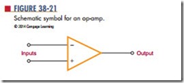
operational amplifiers are usually called op-amps. An op-amp is a very high gain amplifier used to amplify both AC and DC signals. Typically, op-amps have an output gain in the range of 20,000 to 1,000,000 times the input. Figure 38-21 shows the schematic symbol used for op-amps. The negative (2) input is called the inverting input and the positive (1) is called the noninverting input.
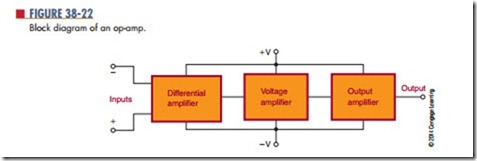
Figure 38-22 is a block diagram of an op-amp. The op-amp consists of three stages. Each stage is an amplifier with some unique characteristic.
The input stage is a differential amplifier. It allows the op-amp to respond only to the differences between input signals. Also, the differential amplifier amplifies only the differential input voltage and is unaffected by signals common to both inputs. This is referred to as common-mode rejection. Common-mode rejection is useful when measuring a small signal in the presence of 60-hertz noise. The 60-hertz noise common to both inputs is rejected, and the op-amp amplifies only the small difference between the two inputs. The differential amplifier has a low-frequency response that extends down to a DC level. This means
that the differential amplifier can respond not only to low-frequency AC signals but to DC signals as well.
The second stage is a high-gain voltage amplifier. This stage is composed of several Darlington-pair transistors. This stage provides a voltage gain of 200,000 or more and supplies most of the op-amp’s gain.
The last stage is an output amplifier. Typically, this is a complementary emitter-follower amplifier. It is used to give the op-amp a low output impedance. The op-amp can deliver several milliamperes of current to a load.
Generally, op-amps are designed to be powered by a dual-voltage power supply in the range of 65 to 615 volts. The positive power source delivers 15 to 115 volts with respect to ground. The negative power source delivers 25 to 215 volts with respect to ground. This allows the output voltage to swing from positive to negative with respect to ground. However, in certain cases, op-amps may be operated from a sin- gle voltage source.
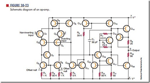
A schematic diagram of a typical op-amp is shown in Figure 38-23. The op-amp shown is called a 741. This op-amp does not require frequency compensation, is short-circuit protected, and has no latch-up problems. It provides good performance for a low price and is the most commonly used op-amp. A device that contains two 741 op-amps in a single package is called a 747 op-amp. Because no coupling capacitors are used, the circuit can amplify DC signals as well as AC signals.
The op-amp’s normal mode of operation is a closed loop. The closed-loop mode uses feedback, as com- pared to the open-loop mode, which does not use feedback. A lot of degenerative feedback is used with the closed-loop mode. This reduces the overall gain of the op-amp but provides better stability.
In closed-loop operation, the output signal is applied back to one of the input terminals as a feedback signal. This feedback signal opposes the input signal. There are two basic closed-loop circuits: inverting and noninverting. The inverting configuration is more popular.
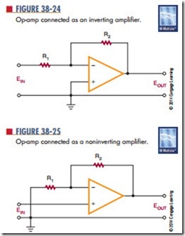
Figure 38-24 shows the op-amp connected as an inverting amplifier. The input signal is applied to the op-amp’s inverting (2) input through resistor R1.
The feedback is provided through resistor R2.The signal at the inverting input is determined by both the input and output voltages.
A minus sign indicates a negative output signal when the input signal is positive. A plus sign indicates a positive output signal when the input signal is negative. The output is 180° out of phase with the input. Depending on the ratio of resistor R2 to R1, the gain of the inverting amplifier can be less than, equal to, or
greater than 1. When the gain is equal to 1, it is called a unity-gain amplifier and is used to invert the polarity of the input signal.
Figure 38-25 shows an op-amp connected as a noninverting amplifier. The output signal is in phase with the input. The input signal is applied to the op-amp’s noninverting input. The output voltage is divided between resistors R1 and R2 to produce a
voltage that is fed back to the inverting (2) input. The
voltage gain of a noninverting input amplifier is always greater than 1.
The gain of an op-amp varies with frequency. Typically, the gain given by a specification sheet is the DC gain. As the frequency increases, the gain decreases. Without some means to increase the bandwidth, the op-amp is only good for amplifying a DC signal. To increase the bandwidth, feedback is used to reduce the gain. By reducing the gain, the bandwidth increases by the same amount. In this way, the 741 op-amp band- width can be increased to 1 megahertz.
Besides its use for comparing, inverting, or noninverting a signal, the op-amp has several other applications. It can be used to add several signals together, as shown in Figure 38-26. This is referred to as a summing amplifier. The negative feedback holds the inverting input of the op-amp very close to ground potential. Therefore, all the input signals are electrically isolated from each other. The output of the amplifier is the inverted sum of the input signal.
In a summing amplifier, the resistor chosen for the noninverting input-to-ground is equal to the total parallel resistance of the input and feedback resistances. If the feedback resistance is increased, the circuit can provide gain. If different input resistances are used, the input signals can be added together with different gains.
Summing amplifiers are used when mixing audio signals together. Potentiometers are used for the input resistances to adjust the strength of each of the input signals.
Op-amps can also be used as active filters. Filters that use resistors, inductors, and capacitors are called passive filters. Active filters are inductorless filters using integrated circuits. The advantage of active filters is the absence of inductors, which is handy at low frequencies because of the size of inductors.
There are some disadvantages when using op-amps as active filters because they require a power supply, can generate noise, and can oscillate due to thermal drift or aging components.
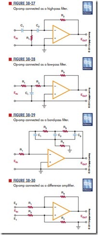
Figure 38-27 shows an op-amp used as a high-pass filter. A high-pass filter rejects low frequencies while passing frequencies above a certain cut-off frequency. Figure 38-28 shows an op-amp used as a low-pass filter. A low-pass filter passes low frequencies while blocking frequencies above the cut-off frequency. Figure 38-29 shows an op-amp used as a band-pass filter. A band-pass filter passes frequencies around some central frequency while attenuating both higher and lower frequencies.
greater than 1. When the gain is equal to 1, it is called a unity-gain amplifier and is used to invert the polarity of the input signal.
Figure 38-25 shows an op-amp connected as a noninverting amplifier. The output signal is in phase with the input. The input signal is applied to the op-amp’s noninverting input. The output voltage is divided between resistors R1 and R2 to produce a voltage that is fed back to the inverting (2) input. The voltage gain of a noninverting input amplifier is always greater than 1.
The gain of an op-amp varies with frequency. Typi- cally, the gain given by a specification sheet is the DC gain. As the frequency increases, the gain decreases. Without some means to increase the bandwidth, the op-amp is only good for amplifying a DC signal. To increase the bandwidth, feedback is used to reduce the gain. By reducing the gain, the bandwidth increases by the same amount. In this way, the 741 op-amp band- width can be increased to 1 megahertz.
Besides its use for comparing, inverting, or noninverting a signal, the op-amp has several other applications. It can be used to add several signals together, as shown in Figure 38-26. This is referred to as a
Questions
1. What is an op-amp?
2. Draw a block diagram of an op-amp.
3. Briefly explain how an op-amp works.
4. What is the normal mode of operation for an op-amp?
5. What type of gain can be obtained with an op-amp?
6. Draw schematic diagrams of the following:
a. Inverting amplifier
b. summing amplifier
c. High-pass filter
d. Band-pass filter
e. Difference amplifier
