![]() TURBINE-GENERATOR COMPONENTS: THE STATOR
TURBINE-GENERATOR COMPONENTS: THE STATOR
Stator Core
The core laminations are normally 0.35 or 0.5 mm thick. They are coated with thin layers of baked-on insulating varnish. Core flux tests are done on the complete core with a flux density of 90 to 100 percent of the rated value. If there is contact between two adjacent plates, local hot spots will develop. The stator bore is scanned using an infrared camera to identify areas of higher-than-normal temperature during such a test. A bonding agent is used in some designs to ensure that individual plates and particularly the teeth do not vibrate independently. Packing material is used to correct any waviness in core buildup.
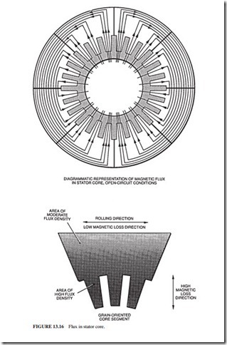
Some designs use grain-oriented sheets of steel. They have deliberately different mag- netic properties in the two perpendicular axes (Fig. 13.16). The low-loss orientation is arranged for the flux in the circumferential direction. This allows higher flux density in the back of the core compared with nonoriented steel, for the same specific loss. The core plates of grain-oriented steel are specially annealed after punching.
The net axial length of magnetic steel that the flux can use is less than the measured stacked length by a factor of 0.9 to 0.95. This is known as the stacking factor. This is caused by the varnish layers and airspaces between the laminations due to uneven plate thickness and imperfect consolidation.
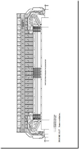
Hysteresis and eddy current losses in the core constitute a significant portion of the total losses. In some designs, the heat produced by these losses is removed by hydrogen circu- lating radially through the ducts and axially through holes (Fig. 13.17).
Thermocouples are installed in the hottest areas of the core. If a hot spot develops in ser- vice, it will not normally be detected by existing thermocouples. A flux test is the way to detect a hot spot. If accidental contacts occur at the tooth tips or there is damage to the slot surfaces, circulating currents could occur. The magnitude of the current depends on the contact resistances between the back of the core plates and the core frame bars on which the plates are assembled. In most designs, all these bars (except for the one which grounds the core) are insulated from the frame to reduce the possibility of circulating currents.
Core Frame
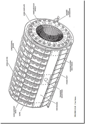
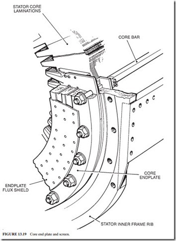
Figure 13.18 illustrates the core frame. The core end plate assembly is normally made from a thick disk of nonmagnetic steel. Conducting screens of copper or aluminum about 10 mm thick cover the outer surfaces of the core end plates (Fig. 13.19). They are called the end plate flux shield. The leakage flux creates circulating currents in these screens. These cur- rents prevent the penetration of an unacceptable amount of flux into the core end plate or the ends of the core.
Stator Winding
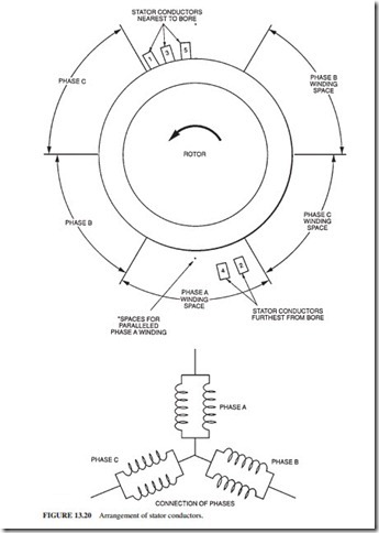
In large two-pole generators, the winding of each phase is arranged in two identical parallel circuits, located diametrically opposite each other (Fig. 13.20). If the conductor is made of an assembly of separate strips, the leakage flux (the lines of induction that do not engage the rotor) density of each strip increases linearly with distance from the bottom strip (Fig. 13.21). This alternating leakage flux induces an alternating voltage along the lengths of the strips that varies with the square of the distance of the strip from the bottom of the slot. If
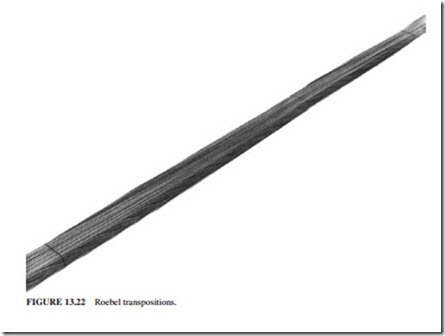
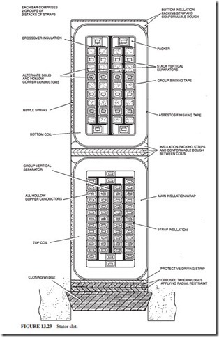
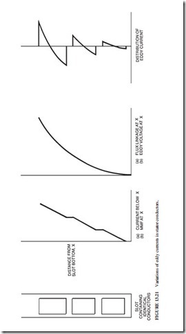 a solid conductor is used, or if the strips are parallel to each other and connected together at the core ends, currents will circulate around the bar due to the unequal voltages. This will cause unacceptable eddy current losses and heating. This effect is minimized by dividing the conductor into lightly insulated strips. These strips are arranged in two or four stacks in the bar width. They are transposed along the length of the bar by the Roebel method (Fig. 13.22). Each strip occupies every position in the stack for an equal axial distance. This arrangement equalizes the eddy current voltages, and the eddy currents will not circulate between the strips. Demineralized water circulates in the rectangular section tubes to remove the heat from the strips (Fig. 13.23).
The conductors are made of hard-drawn copper having a high conductivity. Each strip has a thin coating of glass-fiber insulation. The insulation wound along the length of the bar consists of a tape of mica powder loaded with a synthetic resin, with a glass-fiber backing. Electrical tests are performed to confirm the integrity of the insulation. A semiconducting material is used to treat the slot length of each bar to ensure that bar-to-slot electrical dis- charges do not occur. The surface discharge at the ends of the slots is limited by applying a high-resistance stress grading finish.
The bars experience large forces because they carry large currents and they are placed in a high flux density. These forces are directed radially outward toward the bottom (closed end) of the slot. They alternate at 120 Hz. The closing wedges are not therefore needed to restrain these bars against these forces. However, the bars should not vibrate. The wedges are designed to exert a radial force by tapered packers or by a corrugated glass spring member. Some designs have a sideways restraint by a corrugated glass spring packer in the slot side. Insulation mate- rials consisting of packers, separators, and drive strips are also used in the slot (Fig. 13.23).
The stator winding electrical loss consists of I2R heating (R is measured using the dc resistance of the winding phases at operating temperature) and stray losses which include:
1. AC resistance that is larger than dc resistance (skin effect).
2. Eddy currents (explained earlier).
3. Currents induced in core end plates, screens, and end teeth.
4. Harmonic currents induced in the rotor and end ring surfaces.
5. Currents induced in the frame, casings, end shields, fan baffles, etc. Appropriate cool- ing methods are needed for these losses in order to avoid localized hot spots.
End Winding Support
Bands of conductors are arranged side by side in the end windings. They all carry the same currents (some are in phase with each other and others are not). Large electromagnetic forces are produced in the end windings during normal operation, and especially during fault conditions when large current peaks occur. The end turns must be strongly braced to withstand these peak forces and minimize the 120-Hz vibrations.
A large magnetic flux is produced in the end regions by the mmf in the end windings of the stator and rotor. Metallic components cannot be used to fasten the end winding because
1. They would have eddy currents induced in them. This will cause additional loss and possibly hot spots.
2. Metallic components also vibrate and tend to become loose, or wear away their sur- rounding medium.
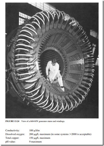
Therefore, nonmetallic components such as molded glass fiber are normally used. Large support brackets are bolted to the core end plate. They provide a support for a large glass- fiber conical support ring (Fig. 13.24). The vibration of the end windings must be limited because it can create fatigue cracking in the winding copper. This can have particularly serious consequences if it occurs in a water-carrying conductor because hydrogen will leak into the water system. Resonance near 120 Hz must be avoided because the core ovalizing and the winding exciting force occur at this frequency. Vibration increase in the end wind- ings due to slackening of the support is monitored by accelerometers. The amplitude of vibration depends highly on the current. Any looseness developed after a period of opera- tion is corrected by tightening the bolts, inserting or tightening wedges, and/or pumping a thermosetting resin into rubber bags located between conductor bars.
Electrical Connections and Terminals
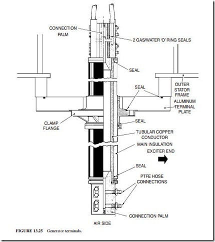
The high end (line end) conductor bars and the low voltage end (neutral end) of a phase band are electrically connected to tubular connectors. These connectors run circumferentially behind the end windings at the exciter end to the outgoing terminals. The connectors have internal water cooling. However, they must be insulated from the line voltage. Figure 13.25 illustrates a terminal bushing. It is a paper-insulated item, cooled internally from the stator winding water system. The insulation is capable of withstanding the hydrogen pressure in the casing without having any leakage.
Stator Winding Cooling Components
Demineralized water is used for cooling the stator windings. It must be pure enough to be electrically nonconducting. The water is degassed and treated continuously in an ion exchanger. These are the target values:
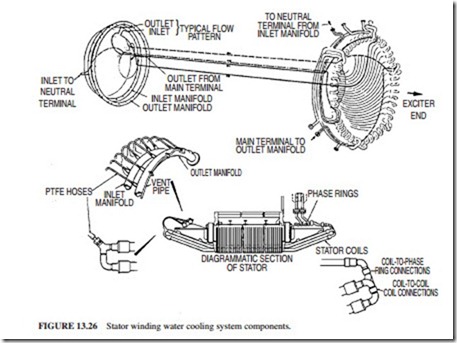
These levels have proved to have no aggressive attack on the winding copper after many years of service. Water enters one or more manifolds made of copper or stainless steel pipes. The manifolds run circumferentially around the core end plate. Flexible PTFE hoses connect
the manifolds to all water inlet ports on the stator conductor joints. In a two-pass design, water flows through both bars in parallel. It is then transferred to the two connected bars at the other end. The water returns through similar hoses to the outlet manifold (Fig. 13.26).
The hydrogen is maintained at a higher pressure than the water. If a leak develops, hydro- gen enters the water. The winding insulation will be damaged if the water enters the hydrogen system. The water temperature increases by less than 30°C. The inlet temperature of the water
is 40°C. There is a significant margin before boiling occurs at 115 to 120°C (at the working pressure). The water temperature of each bar is monitored by thermocouples in the slots or in the water outlets. This allows detection of reduced water flow.
Hydrogen Cooling Components
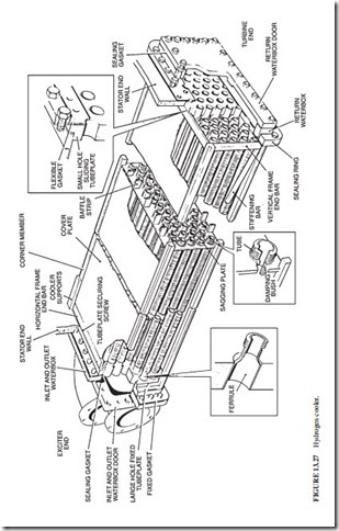
Hydrogen is brought into the casing by an axially oriented distribution pipe at the top. Carbon dioxide is used to scavenge the hydrogen (air cannot be used for this function because an explosive mixture of hydrogen and oxygen will form when the volumetric con- centration is between 4 and 76 percent). The carbon dioxide is admitted through a similar pipe at the bottom. The rotor fans drive hydrogen over the end windings and through the cores of the stator and rotor. During normal operation, the hydrogen temperature increases by about 25°C during the few seconds required to complete the circuit. Two or four cool- ers are mounted inside the casing. They consist of banks of finned or wire-wound tubes. The water flows into the tubes while hydrogen flows over them (Fig. 13.27).
The headers of the coolers are accessible. The tubes can be cleaned without degassing the casing. The supports of the tubes and the cooler frame are designed to avoid resonance near the principal exciting frequencies of 60 and 120 Hz. It is important to prevent mois- ture condensation on the stator end windings (electrical breakdown can occur). The dew point of the hydrogen emerging from the coolers is monitored by hygrometers. This dew point must be at least 20°C lower than the temperature of the cooled hydrogen emerging from the coolers. During normal operation, the stator winding temperature is above 40°C. Thus if condensation occurred, it will be on the hydrogen coolers first. During start-up, the
cooling water of the stator windings is cold. It is preheated electrically, or circulated for a period of time to increase the winding temperature before exciting the generator. This pre- vents the possibility of having condensation on the windings.
Stator Casing
The stator core and core frame are mounted inside the casing. The casing must withstand the load and fault torques. It must also provide a pressure-tight enclosure for the hydrogen. Annular rings and axial members are mounted inside the casings to strengthen them and allow the hydrogen to flow (Figs. 13.28 and 13.29).
The end shields are made of thick circular steel plates. They are reinforced by ribs to withstand the casing pressure with minimal axial deflection. The stationary components of the shaft seal are housed in the end shields. The outboard bearing is also housed inside the end shields in some designs. The sealing of the end shield and casing joints must be leak- free against hydrogen pressure.
A hydrostatic pressure test is conducted on the whole casing. The casing must also be leak-tight when the hydrogen pressure drops from 4 to 0.035 bar in 24 h. Any leaks of oil or water are drained from the bottom of the casing to liquid leakage detectors. These detec- tors initiate an alarm. A temperature sensor is installed at the CO2 inlet. It initiates an alarm if the incoming CO2 has not been heated sufficiently. Cool gas can create unacceptably high localized thermal stresses. Electric heaters are mounted in the bottom half of the casing. They prevent condensation during outages.
