Selector Switches
Selector switches are operated by turning a knob instead of pushing a button. A very common selector switch is the MAN-OFF-AUTO switch. MAN stands for Manual and AUTO stands for Automatic. This is
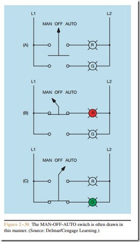
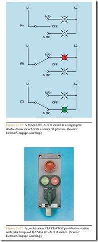
a single-pole double-throw switch with a center off position, as shown in Figure 2 – 29. When the switch is in the OFF position, as shown in Figure 2 – 29A, neither indicator lamp is turned on. If the switch is moved to the MAN position, as shown in Figure 2 – 29B the red lamp is turned on. If the switch is set in the AUTO position, Figure 2 – 29C, the green lamp is turned on. Another symbol often used to represent this type of switch is shown in Figure 2 – 30. A combination START-STOP push-button station, pilot lamp, and HAND-OFF-AUTO switch is shown in Figure 2 – 31.
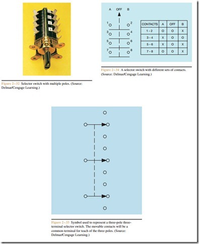
Selector switches often contain multiple contacts and multiple poles (Figure 2 – 32). A symbol used to represent a selector switch with three poles, each having three terminals, is shown in Figure 2 – 33. This selector
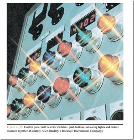
switch contains a common terminal for each of the three poles. The common terminal is connected to the movable contact. A different type of selector switch is shown in Figure 2 – 34. Switches of this type are often supplied with a chart or truth table indicating connections between contacts when the switch is set in different positions. In this example, there is no connec- tion between any of the contacts when the switch is set in the OFF position. When the switch is set in position A there is connection between contacts 3 and 4, and 5 and 6. When the switch is set in position B there is connection between contacts 1 and 2, 5 and 6, and 7 and 8. It is not uncommon to see a combination of selector switches, push buttons, and meters mounted on a single control panel (Figure 2 – 35).
Related posts:
Incoming search terms:
- selector switch function
- auto manual selector switch
- selector switch auto manual
- selector switch diagram
- auto manual selector switch wiring diagram
- 2 position selector switch wiring diagram
- auto manual switch
- auto manual selector switch wiring
- selector switch 3 position wiring diagram
- function of selector switch
- Selector switch operation
- auto manual
- selector switch wiring diagram
- how to wire auto manual selector switch
- selector switch wiring
- selector switch auto off manual
- operation of selector switch
- selector switch connection
- selector switches four position 12 poles
- function of a selector switch
- manual auto switch multiple devices
- manual on auto off 3 way siwtch
- selector switch
- function of switch general symbol
- uses of selector switch
- Equipment internal wiring mail
- wiring ac control swich of 67 valiant
- A typical Hand-Off-Auto control operation typically requires a ? position selector switch with ? contact(s)
- 3 position selector switch wiring diagram
- selector switch truth table
- auto manual switch connection
- auto manual selector switch diagram
- selecter switch manual automatic off conection
- schematic diagram of auto manual motor control
- 3 phase double water pump motor controls diagram
- how four motor auto control two by two control selector switch
- 2 position selector switch symbol
- electrical symbol three way contactor selector switch
- how to work auto manual switch for control panel
- rotary switch connection
- kind of manual operat selector switch
- MANUAL/ AUTO CIRCUIT WITH 3 MOTORS
- selector switch 2 position wiring diagram
- aduajack auto manual diagram
- SELECTOR SWITCH MANUAL NETRAL AUTO
- selector switch use auto
- selector switch working
- selectors switch ckt diagrams
- rotary switch with auto off manual 2 pole
- 2 position rotary switch wiring diagram