Objectives
• To understand the basics of VSDs
• To understand the basics of converters
• To understand the basics of inverters
• To understand the installation, commissioning, and troubleshooting guidelines.
The need for VSDs
Fixed-speed motors and two-speed motors have been dealt with in previous chapters. Various industrial applications require motion control of machines with the help of such motors. VSDs provide continuous range control over the speed of the machines.
Some applications, such as paper mills, rolling mills, pumps, and machine tools cannot run without these while others, such as centrifugal pumps, can benefit from the energy savings. In general, VSDs are used to perform the following:
• Match the speed of a drive to the process speed requirements
• Match the torque of a drive to the process torque requirements
• Save energy and improve efficiency.
Basic VSD
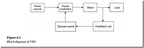
Any basic electrical VSD consists of a motor, drive control unit, sensing unit, and an operator input.
The basic block diagram of a variable speed electrical drive is show in Figure 6.1.
The drive control unit is a device, which modulates power going from the source to the motor. Using the operator panel, one can increase or decrease the speed set point.
A feedback unit gives the drive the actual speed feedback. The power modulator or the drive control unit then controls the speed, torque, and power, along with the direction of the motor and the machine. The power modulator may be used as a single device, for controlling a motor. It may have to be used in a combination type for certain other types of applications. The following are the types of power modulators or converters along with a brief description of each.
Converters
These convert one form of energy into another form, suitable for a motor. They can be defined as assemblies of power electronic components, which convert one or more of the characteristics of an electric power system.
For controlling DC motors, a variable DC voltage is required. For AC motors, a fixed frequency, variable AC voltage, or a variable frequency, variable voltage is required. To fulfill the requirement, the following devices are used. Given below are the various types
of converters and their combinations:
1. AC to DC converters
These are classified as:
• Uncontrolled diode rectifier
• Half controlled rectifier
• Full controlled rectifier
• Rectifier with self-commutated devices.
In an uncontrolled rectifier, the fixed DC voltage at output is different from the AC supply at input. In a half-controlled rectifier, the variable DC voltage at output with a positive voltage and current is called a single quadrant drive. With a full controlled rectifier, the DC voltage of positive/negative polarity and the current in a positive direction is called a double quadrant drive. A full controlled rectifier has commutating devices such as the GTO (gate turn-off thyristors) and power transistors. It can be a single or a double quadrant drive.
If used with a full controlled rectifier, it can then provide four quadrant functionality, i.e., voltage as well as current in both directions.
2. DC to DC converters
Also known as choppers, these enable the variable DC voltage at output, from the fixed DC voltage given at input.
3. DC to AC converters or inverters
The usage of inverters ensures a variable-frequency AC voltage at output from a fixed DC voltage given at input.
It is either a voltage source or a current source type. The output voltage or current can be changed along with the frequency by varying the DC input voltage. This occurs by feeding the DC voltage to the inverter through a rectifier. Variable voltage, variable- frequency AC voltage can be obtained using the PWM (pulse width modulation) for controlling the inverter.
4. Cycloconverter
The usage of cycloconverters ensures a variable voltage, variable-frequency AC voltage at output from a fixed voltage, and frequency AC voltage given at input.
These are built using thyristors, the firing of which is controlled by a control unit.
The following section details the various power electronic basic components. These components form a basic part of all circuits.


