Fuel Injection
The internal combustion engine’s purpose is to produce horsepower to drive the vehicle. It does so by producing heat which, in turn, is the by product of the engine’s internal combustion of an air-fuel mixture. All gasoline-powered automotive engines must get this air and fuel (usually gaso line) into their combustion chambers.
The conventionally carbureted automotive en gine depends upon the vacuum created by the downstroke of its pistons to suck the air-f uel mix ture into the combustion chambers.
Generally speaking, this is a good method of getting the job done. It is a relatively simple sys tem that works under most conditions in a satis factory manner. However, the carburetor is not a very sophisticated device for metering fuel and while it does do the job, it does not do it in the most efficient manner possible. In fact, the impre cise nature of the carbureted intake system leads to wasted fuel and an overabundance of exhaust emissions. In fact, in the areas of exhaust emission control and high performance, the carburetor has clearly been eclipsed by a more precise fuel meter ing system which is fuel injection.
The fuel injected engine utilizes that same vac uum condition to suck in ambient air. But the fuel is squirted either into a modified intake “mani fold,” or directly into each cylinder head intake port, or through a fuel injection nozzle directly into the combustion chamber.
Thus, though fuel injected engines do depend on engine vacuum to suck air into the cylinders, the fuel is delivered via a pump through the in jection system and is non-dependent on engine vacuum. This aHows precise fuel metering to each cylinder. With fuel injection, the fuel is delivered to each cylinder. This permits precise fuel distribution, vastly improved fuel use efficiency, and therefore , much better economy plus a lessened output of harmful emissions.
Fuel injection is interrelated with reduced harm ful emissions because a fuel injected engine can run leaner. That is, the air-fuel ratio contains more air and less fuel than “normal.” Furthermore, the air-fuel ratio can be more tightly controlled and precisely tailored to the engine’s needs than can the ratio on a carbureted engine. An engine’s “optimum” air-fuel ratio is the same whether the engine is carbureted or injected. The ratio re quirem nt changes according to whether the en gine is idling, accelerating, or cruising. The opti mum ratio is about 9.5-to-1 at idle (for pre-1968 automobiles), whereas emission-controlled late model engines require a 14-to-1 ratio at idle. Cruising mixtures as lean as 16-to-1 are required on emissions engines operating near sea level. Suffice it to say that, generally, 11.5-to-1 is rich (that is, less air in the ratio than “normal”), and that 15-to-1 is a lean mixture because there’s more air than “normal” in the ratio, and thus less fuel.
A further advantage of fuel injection is its more even distribution of fuel which, in turn, enables fuel injected engines to meet stringent emission regulations. This is because fuel injected engines discharge their fuel right at or quite close to the intake valve and do not depend upon air velocity for airjfuel mixing in the intake manifold or combustion chamber.
By the way, these same properties are what make fuel injection systems so popular in racing engines. However, there tl1e injection systems are tuned for rich mixtures and more engine power, rather than lean mixtures, for better emission control.
In short, fuel injection helps control the efficient burning of the air-fuel mixture. And high effi ciency can work for you whether you are after performance, economy or lower emissions.
A Short History
There are presently various types of mechanical and electronically controlled fuel injection sys tems utilized by domestic and foreign automakers. And you may think of fuel injection as a rela tively new development, yet, various manufac turers have been trying to circumvent the car buretor for more than 50 years.
Bosch began in 1912 in its experiments with fuel injection concepts primarily for increased engine power output, which, until the recent and overrid ing emissions requirements, was the major thrust of fuel injection development. By 1932 Bosch was ready to series-produce piston operated aircraft engines equipped with gasoline injection systems. Bosch’s first automotive injection setups for series production were introduced in 1952.
The history of American fuel injected engines is integrally connected to racing, units having ap peared as early as the 1940s on Indianapolis and other racing cars.
Enderle and Hilborn fuel injection units first ap peared in the 1940s and became virtual necessities on modem drag racing engines, both naturally as pirated and supercharged. Today’s turbocharged Indianapolis, Formula I, and drag racing engines utilize fuel injection that works in conjunction with superchargers and turbochargers.
Cadillac’s use of a Bendix electronic fuel injec tion system in 1975 was the first employment of domestic fuel injection in an American production automobile since the famous fuel injected Cor vettes passed from the scene in 1965.
The Chevrolet Corvettes employed Rochester fuel injection as an option from 1957 until 1965. The Rochester unit was unique, and originally de signed for extreme cornering situations during rac ing and slalom events, because carburetors just could not function properly under such conditions. The unit, however, not only served diligently in racing for nine years, but also delivered excellent fuel economy and performance on the street.
With Chevrolet leading the way with production line installation of the Rochester fuel injection units on Corvettes and even high performance ver sions of their passenger cars, other American man ufacturers began looking at fuel injection as a performance and an image booster.
Pontiac built 1500 special 1957 Bonneville con vertibles with bucket seats and fuel injected en gines in late 1957 as a test. Although the test seemed successful, and Pontiac announced the in jection option as available for 1958, they never built any 1958 cars with injection, instead going to three 2-barrel carburetion for their top perform ance models.
Also, in 1958, the Rambler Rebel and the Chrysler 300D, both special high performance models, were availa:ble on a limited basis with an electroni cally controlled Bendix Electrojector system. How ever, as production line and field problems devel oped with these early units, they disappeared, leaving only the Corvette Rochester system, which would continue as a regular production option until1965.
In contrast to American auto manufacturers, the imported carmakers have continued on the fuel in jection development road in partnership with the Robert Bosch Corporation.
Bosch and Volkswagen cooperated in the de velopment and 1967 introduction of Bosch’s first real electronically controlled injection system, the D-Jetronic. Various model VWs have used this system ever since.
As more and more automakers came to Bosch and needed different performance characteristics from an electronic fuel injection system, Bosch evolved the L-Jetronic system that is more com mon now than the earlier D-Jetronic.
And when manufacturers asked for a simpler system that could accomplish the same results as the L-Jetronic but without the inherent complexi ties of an electronic brain controlling the system, Bosch developed the K-Jetronic which is a me chanically controlled continuous :Bow injection sys tem.
At present, among U.S. manufacturers, only Cadillac utilizes a fuel injection system. It is man ufactured by Bendix and is electronically con trolled. However, it is expected that this situation will change in the future as more and more manu facturers seek a precise fuel metering system to control engine efficiency and emissions.
Since each system has its own operating charac teristics and components, it will be helpful for you to understand how each system operates. We will not discuss the Bendix Electrojector system since it was only installed on a few cars in 1958 and is not even remembered by most students of auto motive technology.
Rochester System
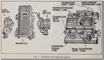
The Rochester fuel injection system was im proved throughout its nine year life cycle. How ever, the basic components and operating princi ples remained the same throughout the nine years,Fig. 1.
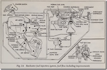
Some of the improvements, Fig. 1A, are as follows:
1. Vent screen and baffle added to the fuel meter providing for a more stable fuel mixture.
2. Choke calibrations improving engine warm-up performance.
3. Solenoid controlled by-pass fuel circuit (for cold engine starting) replacing the manifold vacuum controlled, cranking signal valve cir cuit.
Note that some additional improvements to this system are explained elsewhere in this chapter.
Vent and Baffle
The vent screen is located behind the welsh plug in the discharge port on the spill side of the spill valve. The screen reduces vapors or bubbles being discharged into the bowl, thus stabilizing fuel mixture by providing a more solid fuel to the pump.
The vent baffle is attached to the float side of the fuel meter cover to protect the external vent screen from fuel wetting and provide a more stable idle.
Choke
The addition of a choke piston and the relocation of the choke valve stop (in the diffuser cone) to allow 10° open position allows more initial , choke for initial cold start. The choke piston will
open the choke valve to the 30° open position after the initial cold start.
By-Pass Fuel Circuit
When the by-pass fuel circuit is in operation, the entire output of the engine fuel pump is delivered through a by-pass line directly to th e fuel distribu tor (spider) where the fuel then passes through a ball-check valve and is routed to the nozzle in each cylinder. The control solenoid for the by-pass fuel circuit will be energized to open a fuel valve and provide fuel delivery through this circuit whenever the ignition key is held in the “Start” position and the accelerator pedal is not depressed more than of its total b·avel distance. A microswitch, mounted on the injector throttle linkage (tripped by depressing the accelerator pedal beyond the first third of its travel), will stop all fuel delivery through the by-pass fuel circuit.
SYSTEM COMPONENTS
( 1) the Air Meter, which supplies a vacuum control signal to the fuel meter in response to engine load demand;
(2) the Fuel Meter, which interprets the vac uum control signal from the air meter and regulates the fuel flow to the nozzles ac cordingly; and
( 3) the Intake Manifold, which provides the distribution system with the rammed air flow to the engine cylinders.
Air Meter
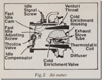
The air meter consists of three main parts-the throttle valve, the cold enrichment valve and dif fuser cone assembly and the air meter body, Fig. 2.
The throttle valve controls the flow of air into the system and is connected mechanically to the accelerator pedal.
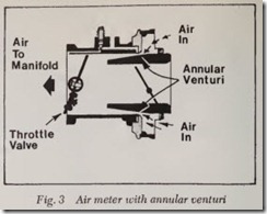
The diffuser cone is suspended in the bore of the air meter inlet. Its design provides a highly effi cient, annular venturi between the air meter body and the cone, Fig. 3. This type of venturi produces the minimum restriction to air flow that is a vital factor in engine breathing capacity.
The air meter body houses the foregoing com ponents plus idle and main venturi signal systems.
Main Venturi Signal
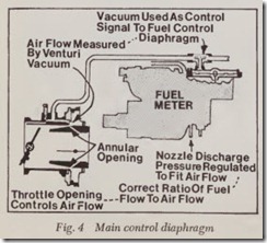
Main venturi vacuum signals are generated at the venturi by air flowing past an annular opening formed between the air meter body and the ma chined piezometer ring. The signal is then trans mitted thru a tube to the main control diaphragm in the fuel meter, Fig. 4.
The venturi vacuum signal (except at idle speeds) will always be a direct measure of air flowing into the engine; therefore the signal can be used to automatically control fuel air ratios to the engine cylinders.
Idle Air
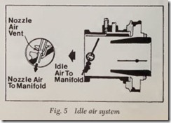
Approximately 40% of the air requirement at idle enters the engine by way of the nozzle blocks from an air connection tapped into the air meter body, Fig. 5. The remaining air is controlled by adjusting throttle valve position with the posi tive idle stop screw located externally on the air meter. Turning the screw in increases speed and turning the screw out decreases idle speed.
Fuel Meter
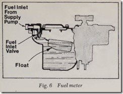
The fuel meter contains a float controlled fuel reservoir very similar to that used in conventional carburetion, Fig. 6. Fuel is supplied to the fuel meter by the existing engine fuel pump. Fuel enters the meter thru a 10 micron filter, passes thru the fuel inlet valve, and spills directly into the main reservoir of the fuel meter where the high pressure wobble pump picks it up
High Pressure Wobble Pump
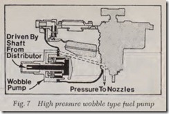
The spur gear type pump has been replaced in the 1963 model with a high pressure wobble pump. The pump is located in the lower part of the fuel meter main reservoir and is completely submerged at all times, Fig. 7. The pump is powered by a flexible shaft driven by the distributor and rotates at “M. engine speed. Nominal fuel pressures vary up to 200 psi, depending on engine speed. Fuel sup ply not used by the engine is spilled back into the fuel meter by means of the fuel control system.
Fuel Control System
Fuel pressure (flow) from the positive displace ment wobble pump must be regulated to provide the correct flow to the nozzles.
The Rochester Injection System is regulated by the amount of fuel spilled or bypassed away from the nozzle circuits.
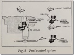
The 1963-65 model was designed with a recir culating fuel flow from the high pressure pump to the nozzle distributor block and back to the fuel meter spill ports. A three piece valve is located in series between the wobble pump, nozzle distribu tor block and spill ports, Fig. 8. When a high fuel flow is required, the spill plunger or disc is moved downward, closing off spill ports to the fuel meter reservoir. The back pressure now created forces the fuel through a spring loaded check valve in the nozzle distributor block and into the nozzle feed lines. According to engine requirements, variation in back pressure is achieved by the po sitioning of the spill disc. With increased pressure less fuel can return to the bowl through the re stricted spill ports. Correspondingly, on lower fuel requirements the spill disc is progressively raised, decreasing back pressure and allowing more fuel to return through the spill ports.
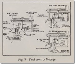
The accelerator pedal is not directly connected to the spill plunger. Fuel control is accomplished by a very precise linkage system. This linkage system is carefully counterbalanced so that the only forces acting on the system are fuel pressure and diaphragm vacuum. This precision balancing of the linkage makes the unit extremely sensitive to the slightest change in venturi vacuum signal on the main control diaphragm.
The control linkage is located in the fuel meter, Fig. 9. One end of the fuel control lever rests di rectly on the spill plunger head and controls spill plunger or disc position. The other end of the con trol lever is connected by a link to the main con trol diaphragm. The control lever pivots on an other lever called the ratio lever. When the dia phragm pulls the control lever upward, the roller end pushes the spill plunger or disc downward, closing off the spill ports and thus increasing fuel How to the nozzles. When the diaphragm allows the control lever to fall, fuel pressure forces the spill plunger or disc upward and opens the spill ports to by-pass fuel into the reservoir, reducing fuel How to the nozzles.
Operating Principles
Starting System
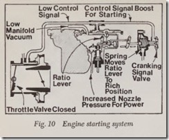
Cold engine starting conditions require extra fuel to compensate for poor fuel evaporation . Pumping the accelerator will not provide this fuel because there is no accelerator pump as in con ventional carburetion. The accelerator should be depressed once and then released, allowing the throttle to be preset for starting by the fast idle cam. During cranking rpm, the signal generated at the idle needle and air meter venturi is very low and has to be boosted. This boost comes from a normally spring loaded open cranking signal valve located at the enrichment diaphragm housing, Fig.10.
The open cranking signal valve allows direct manifold cranking vacuum to react on and lift the main control diaphragm closing the spill valve. In addition, the enrichment diaphragm is spring load ed to hold the ratio lever at the rich or “Power” stop, Fig. 10, thus maximum fuel How available at cranking speeds is directed to the nozzles. Imme diately upon starting, or when manifold vacuum reaches 1″ Hg, the engine manifold vacuum over comes the springs in the cranking signal valve and enrichment diaphragm, and the Fuel Injector oper ates on the normal idle system.
Cold Enrichment System
The idle system used on the latest design Fuel Injector has been greatly simplified. The newly de signed diffuser cone incorporates a “choking” valve that simplifies the cold enrichment system found on early models.
To achieve a maximum signal at the control dia phragm during cold engine operation, the choke valve is held in a closed position by a thermostatic coil. This forces all air flow through the venturi thereby creating a high signal, even at relatively slow engine speeds.
As engine heat relaxes the thermostat and allows the choke valve to open, less air passes thru the venturi decreasing the generated signal.
Idle System
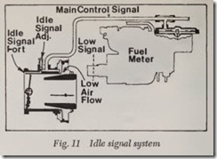
Fuel control during warm-engine-idle, is ac complished thru the idle circuit signal acting on the main control diaphragm, Fig. 11. The ratio lever is at the “Economy” stop. Air for combustion now enters as previously described, through the idle circuit and the vented nozzle blocks.
Acceleration
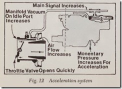
At normal driving speeds, acceleration is instan taneous. As the throttle is opened, three operations take place to provide the necessary added fuel during acceleration, Fig. 12:
1. opening the throttle valve causes an increase in air flow which increases the venturi signal at the main diaphragm, 2. the momentary reduction of manifold vacuum causes the ratio lever to move to the power stop,3. the calibrated restriction in the main control signal circuit retains any signal left prior to the acceleration demands, thus adding to the total sig nal before it bleeds thru the restriction.
Power
The fueljair mixtures necessary during power demands are similar to acceleration demands. The quickly obtained wide-open-throttle causes a re duction in manifold vacuum and the ratio lever moves to the power stop.- More important is the radically increased air flow and hence venturi sig nal directed to the main diaphragm.
Hot Starting and Unloading
Hot starting and unloading operations definitely require no “extra fuel.”
For hot starting and unloading, the throttle valve should be held from half to wide open.
NOTE: ‘If start does not occur in a few seconds, do not continue cranking. Stop and repeat starting procedures.
Hot Idle Compensator
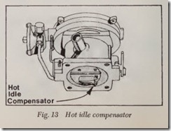
During extreme heat conditions, fuel vapors can cause rich idling which results in engine roughness and stalling.
A thermostatically operated valve is located on the top side of the air meter throttle valve. As idling temperatures increase to the activity range of the thermostatic spring, the valve opens expos ing a calibrated orifice thru the throttle valve. A predetermined amount of additional air can now bleed into the over-rich manifold and restore idle mixtures to a correct ratio. Since the compensator is factory calibrated, no adjustment is necessary and should be replaced if defective, Fig. 13.
