DESCRIPTION
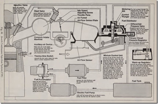
The Bosch Continuous Injection System, Fig. 36, is a mechanically and continuously operating fuel injection system which does not have to be driven by the vehicle engine. The fuel is pumped by an electrically-driven roller cell f uel pump. During operation the intake air quantity is metered by an air-flow sensor installed in front of the throttle pla te. Depending on the position of the accelerator
pedal, which controls the position of the throttle plate, a varied quantity of air is drawn into the engine. Therefore depending on the volume of air metered, a hel distributor meters a quantity of fuel to the individual cylinders through the asso ciated injection valves which produces an opti mum air-fuel mixture with regard to engine power, fuel consumption, and exhaust-gas emission.
The air-flow sensor and the fuel distributor are combined into one assembly, called the mixture control unit. The precisely metered quantity of fuel is fed to the injection valves which con tinuously spray the fuel in finely atomized form into the intake manifold in front of the cylinder intake valves. From there the fuel is drawn into the engine cylinders combined with air when the intake valves open.
AIRFLOW SENSING
Description
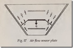
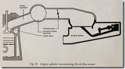
The principle of air-flow sensing in the CIS is comparable to the well-known suspended body principle: a round disc (the air-flow sensor plate) rises in a conical air tunnel until its weight and the force of the air flow against the bottom of the disc are in equilibrium, Fig. 37. If the volume of air drawn into the engine increases, the rate of air flow also increases through the original annular cross-sectional area in the air-flow sensor. As a re sult, the flow force increases, and the air-flow sensor plate is forced farther upward until the original flow rate ( = flow force) exists at the new and larger cross-sectional area in the funnel. Here, the air-flow sensor plate again comes to rest. The position of the air-flow sensor plate in the air fun nel thus represents a measure of the volumetric rate of air flow through the air funnel and is there fore a measure of the quantity of fuel required. The air-flow sensor plate rises a distance approxi mately proportional to the volum-etric rate of air flow, Fig. 38.
Construction
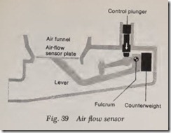
The air-flow sensor, Fig. 39, consists of the air funnel and the air-flow sensor plate mounted on the lever which is supported at its fulcrum. The we ghts of the lever and air-flow sensor plate are balanced by the counterweight. A plunger (the control plunger) operated by the hydraulic pres sure transmits a force opposing the air force through the lever and then to the air-flow sensor plate. The intake air flowing through the air funn l lifts the air-flow sensor plate until the force of this air and the opposing force of the plunger reach equilibrium.
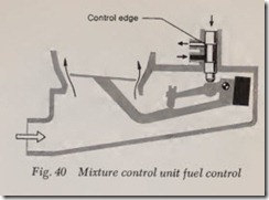
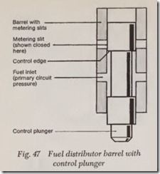
In this position of equilibrium, which is a measure of the volumetric rate of air flow, the control plunger is positioned at a certain point in the fuel distributor, and its horizontal control edge opens the rectangular metering slits by a certain uniform amount, Fig. 40. The fuel which flows through these openings is then fed to the injection valves.
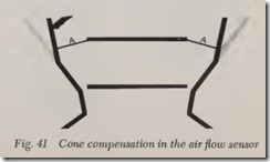
As a result of the linear action of the air-flow sensor and fuel distributor, and because these components are joined by a lever to form a single operating assembly, an initially exact and stable basic matching of air and fuel results for a con stant air factor. The exhaust gas regulations re quirements are achieved in the basic design of the CIS by a modification in the shape of the funnel in the air sensor, Fig. 41. Specifically, in order to match the air-fuel ratios to the various load levels -(idle, part load, full load) the air funnel be comes wider in stages, Fig. 41. In those parts of the funnel where the wall is steeper than in the basic shape, the air-flow sensor plate must b.e forced higher in order to develop a state of eqm librium than would be the case in an air funnel with straight walls. As a result, a richer mixture is developed during idle and full-load. Conversely, if the walls of the funnel rise less steeply (flatter funnel) than in the basic shape, a leaner mixture is developed.
FUEL SUPPLY
When discussing the fuel supply system in the CIS, we must differentiate between the primary fuel circuit and the control circuit. In addition, the pressure in the fuel lines leading to the injec tion valves, must also be considered.
Primary Fuel Circuit
In this circuit, a roller cell pump combined with an electric motor draws the fuel from the fuel tank and pumps it through a fuel accumulator and a fine fuel filter to the fuel distributor, Fig. 36.
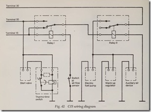
The electric fuel pump is set in operation when the vehicle engine is started, and the power to the pump motor is cut off when the engine stops turn ing. This process is actuated by the air-flow sensor contact through the safety relay, Fig. 42.
The fuel accumulator must fulfill the following three functions:
I. dampen supply pump noise by a built-in fuel spinner;
2. delay the build-up of pressure in the primary fuel circuit when the engine is started-this ensures that the control plunger is in the zero position at this time; and
3. retain pressure in the system after the engine has been turned off in order to ensure good hot restarting performance.
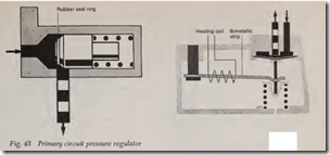
In the fuel distributor, the fuel initially enters a passage which joins the lower chambers of the differential-pressure valves. As a result, the same fuel pressure, held constant by the primary circuit pressure regulator built into the fuel distributor, prevails in each of the lower chambers. This pri mary circuit pressure regulator is designed as a plunger-type regulator and regulates the system overpressure. Excess fuel Haws back through a re turn line under no pressure back to the fuel tank.
When the engine is operating, the fuel passes through the metering slits, to the upper side of the diaphragm of the differential-pressure valves and then flows through the fuel injection lines to the injection valves.
The injection valves are designed so that they finely atomize the fuel even at low fuel flow rates.
A supply line leads from the primary fuel circuit to the start valve.
When the engine is turned off, the primary cir cuit pressure regulator lets the pressure in the sys tem fall rapidly to the opening pressure of the injection valves, then it holds the pressure at this level by means of a rubber valve seat which takes effect at that time, Fig. 43. As a result of the rapid drop of pressure in the fuel supply system, the “dieseling” or “running on” phenomena after the ignition has been turned off which occurs in many vehicles is prevented without additional switching devices.
Control Circuit
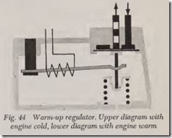
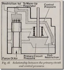
The control circuit branches off from the pri mary fuel circuit through a restriction bore in the fuel distributor. A connection line leads from the fuel distributor to the regulator for the control pressure which is called the warm-up regulator, Fig. 44. At normal operating temperature, the warm-up regulator holds the control pressure con stant, it lowers the control pressure only when the engine is cold and during the warm-up period. The control pressure acts through a damping re striction on the control plunger and thereby devel ops the force which opposes the air force in the air-flow sensor, Fig. 45.
Excess fuel flows from the warm-up regulator under no pressure back to the fuel tank.
The warm-up regulator is mounted on the ve hicle engine in such a way that it can absorb heat from the engine block and thus assume the tem perature of, the engine block. As a result, when the engine is started in the semi-warm condition unnecessary enrichment (causing an over rich con dition) of the fuel is avoided.
The damping restriction over the control plung er performs a special function. Under conditions of pulsating air flow which occur, for example, at a low engine speed and high load, the air-flow sensor plate in the air-flow sensor is deflected too far from its base position. As a result, the mixture is automatically enriched even though the basic setting is for a lean mixture. The function of the damping restriction is to dampen the movement of the air-flow sensor plate during pulsating flow. At the same time, this restriction regulates the dis tance by which the air-flow sensor plate will swing too far, determining the momentary transi tional enrichment of the fuel during acceleration; this restriction therefore creates the conditions necessary for optimum driving performance.
Fuel Distributor
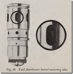
The fuel must be distributed uniformly to the different cylinders in the engine. In the CIS, the assembly designed to do this operates on the basis of simultaneous control of the open cross-sectional
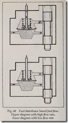
area of metering slits machined into the barrel in the fuel distributor, Figs. 46, 47 and 48. The barrel has as many slot-shaped (rectangular) openings (metering slits) as there are cylinders in the engine. A differential-pressure valve follows each metering slit for purposes of holding the drop in pressure at the metering slits constant at various flow rates. As a result, possible effects of varia tions in the primary system pressure and differ ences in the opening pressure of the injection valves are eliminated. With a constant drop in pressure at the metering slits, the amount of fuel flowing to the injection valves depends only on the open cross-section of these slits. The fuel dis tributor operating characteristic line is therefore linear.
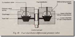
The differential-pressure valve, Fig. 49, is a diaphragm valve consisting of a lower and an upper chamber with a steel diaphragm between them. In the lower chamber the so-called primary system overpressure prevails, while in the upper chamber there is a slightly lower overpressure. The pressure differential is produced by the heli-cal spring built into the upper chamber.
Under these conditions, equilibrium of forces exists at the diaphragm of the differential-pressure valve.
If more fuel flows through the metering slit into the upper chamber, the pressure there rises tern- porarily. The steel diaphragm is forced downward and enlarges the cross-section of the outlet leading to the injection valve until a slight differential pressure again prevails at the metering slit.
At higher rates of fuel flow, the diaphragm opens a larger annular cross-section, so the pres sure differential remains constant. If the rate of fuel flow decreases, the diaphragm decreases the discharge cross-section. The total travel of .the diaphragm is only a few hundredths of a milli meter.
COMPENSATION UNITS
If needed, compensation units are available for the CIS for cold starting, warm-up, and full-load enrichment, Fig. 44. In order to meet the more exacting requirements arising from stricter ex haust gas regulations, for instance during catalytic operation etc., additional compensation and con trol modifications are possible.
Warmup Compensation
During the warmup period of an engine, two compensations are basically required compared with conditions at normal operating temperature:
1. Compensation for condensation losses on the cold walls of the combustion chamber and intake manifold.
2. Compensation for power lost as a result of greater friction.
Compensation is made for condensation losses by a richer mixture. This function is performed by the warm-up regulator. It lowers the pressure applied to the control plunger during the warm-up period, as a result of which the air-flow sensor plate is lifted a greater distance from its rest posi tion by the same rate of air flow, and the open cross-sectional area of the metering slits in the barrel assembly is therefore enlarged.
The change in the control pressure during the warm-up period takes place as follows:
As long as the engine is cold, a bimetallic strip presses against the delivery valve spring. As a re sult, the pressure on the diaphragm is reduced, the discharge cross-section is enlarged and the control pressure is thus lowered. When the engine is started, the electrical system designed to heat the bimetallic strip is switched on. This strip warms up, relaxing the pressure on the delivery valve spring, and at a certain temperature it rises completely up from the spring plate. This means that after the warm-up period the delivery valve spring is fully effective. A fairly high control pres sure must develop before the discharge cross section opens.
Compensation is made for the power lost as a result of greater friction by feeding a larger volume of the air-fuel mixture to the engine than corresponds to the position of the throttle plate. This is done by bypassing the throttle plate with an auxiliary-air device, Fig. 36, in which the cross sectional area of the channel which is open to flow of air is controlled by a pivoted blocking plate with a specially shaped hole; the movement of this plate is dependent on an electrically heated bimetallic strip. At normal operating tem perature this extra channel is closed.
Auxiliary Starting Assembly
The auxiliary starting assembly consists essenti ally of an electromagnetically-operated start valve, Fig. 50, which is switched on at the beginning of the starting process, and a thermo-time switch which limits the duration of time that the valve is open, or at higher temperatures, prevents this valve from opening at all. The start valve sprays additional fuel into the common intake manifold.
Because of the relatively high primary circuit pressure (overpressure), the fuel is well atomized by the swirl nozzle.
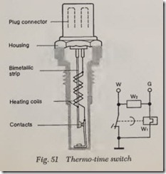
The thermo-time switch, Fig. 51, closes or opens the power circuit leading to the start valve de pending on the engine temperature. During cold starting, the power circuit is interrupted depend ing on the temperature of an electrically-heated bimetallic strip. The thermo-time switch has either a single heating coil Wt, or-if rapid heating is required-two heating coils, wl and w2. When the switching temperature is reached, the con tacts are opened, cutting off power to the start valve. This switches heating coil W2 off. Heating coil W1 holds the contacts open until the end of the starting operation.
Hot or Warm Starting
As a result of suitable design of the various valves and of the fuel accumulator in the system, sufficiently high pressurization is assured even after the engine has been turned off for an ex tended length of time, so that formation of vapor bubbles in the lines is prevented.
CONSTRUCTION OF SYSTEM COMPONENTS
Electric Fuel Pump
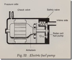
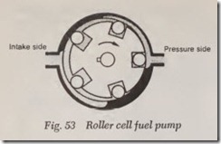
The fuel pump in the CIS is a roller cell pump driven by a permanent-magnet electric motor, Fig. 52. The rotor disc, mounted on the motor shaft, is fitted with metal rollers in notches around its circumference which are pressed against the excentrically designed pump housing by centrifu gal force and act as seals. The fuel is carried in the gaps between the rollers and is then forced into the fuel injection tubing, Fig. 53.
In this system, the fuel flows directly around the electric motor. There is no danger of explo sion, however, because there is never a com bustible mixture inside the pump housing. This pump delivers several times the quantity of fuel actually required, so the excess fuel is diverted at the primary circuit pressure regulator and it flows under no pressure back to the fuel tank.
Fuel Accumulator
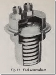
The fuel accumulator is divided by a diaphragm into the accumulator chamber and the spring chamber, Fig. 54. In front of the diaphragm is a steel partition with a plate valve for fuel intake and a restriction bore for return of the fuel. The – diaphragm chamber is filled through the plate valve and a large hole. The diaphragm itself bulges downward against the pressure of the spring until it reaches the spring plate limit stop on the accumulator housing under the diaphragm; it remains in this position as long as the vehicle engine is operating. When the engine is turned off, the space inside the fuel accumulator becomes available for the system, and the fuel flows back through the restriction.
Fuel Filter
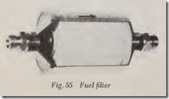
The fuel filter is a line filter with a paper car tridge, Fig. 55. Following the paper cartridge is a fine-mesh filter designed to catch any particles which may be released by the paper cartridge. For this reason, the direction of flow printed on the housing must be strictly adhered to. If necessary, the entire filter should be replaced. The filter is connected at both ends into the fuel system by means of threaded connectors.
Mixture Control Unit
The main components in the mixture control unit are the air-flow sensor and the fuel distribu tor, Fig. 36.
The relationship between the air-flow sensor and the fuel distributor is set by means of the idle mixture adjusting screw. When this screw is turned to the right a richer mixture is produced,
when turned to the left, a leaner mixture is pro duced. The idle mixture is adjusted with this screw.
Warmup Regulator
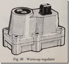
A two-hole Bange is used to mount the warmup regulator on the engine, Fig. 56; the electrical connection is made by means of a plug connector. The control pressure is low with a very cold en gine. As the engine warms up, this pressure rises continuously to the normal overpressure. The re turn line is connected to the smaller threaded connection.
Injection Valve
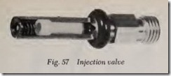
The injection valve, Fig. 57, opens automatically by fuel pressure and has no metering function. It is supported in a specially shaped molded rubber part. This valve is pressed, not screwed, into place. The hexagonal section on the valve shaft is provided to hold the valve stationary while the fuel line is attached. The fuel is finely atomized, even at a low rate of How.
Start Valve
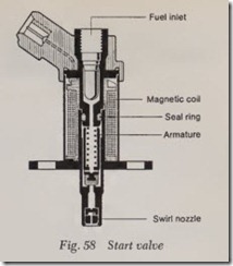
In the elecbically-operated start valve, Fig. 58, a helical spring presses the movable armature in the magnetic circuit together with the seal against the valve seat and closes the fuel inlet. When the armature is drawn back, however, the fuel inlet is opened. The fuel then Bows along the sides of the armature to the swirl nozzle. There, a swirling motion finely atomizes the fuel.
Thermo- Time Switch
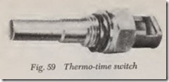
The thermo-time switch, Fig. 59, limits the length of time that the start valve remains open, and at higher temperatures it prevents the start valve from opening at all. This switch is therefore mounted on the engine in such a way that it can absorb heat from the engine, Fig. 60.
Auxiliary-Air Device
The auxiliary-air device, Fig. 61, is mounted by means of a two-hole Bange at some point on the engine where the temperature is characteristic of the engine’s operating condition. A plug is pro vided for the electrical connection.
ELECTRICAL CIRCUIT
The air-How sensor plate in the air-How sensor activates a switch which is closed when the engine is turned off. When the air-How sensor plate rises from its seat, however, the ground line from Relay I is opened.
When the ignition is switched on (Terminall5),
Relay I is energized. Relay II remains at rest, how ever, and the electric fuel pump remains switched off.
When the engine is started (Terminal 50), the control current for Relay II Bows through the working contact of Relay I, and the electric fuel pump is switched on through the working contact of Relay II. At the same time, current starts to £ow to the warm-up regulator and to the auxiliary-air device. The start valve is also switched on at this time through a thermo-time switch.
As soon as the engine draws in air, the air-How sensor plate in the air-How sensor rises from its seat and opens the ground line from Relay I. Relay I is then de-energized and returns to its off position. Relay II remains energized, however, and the electric fuel pump continues to operate.
If the engine comes to a stop as a result of exceptional conditions, the electric fuel pump is also automatically stopped .even though the ignition is still turned on. This results from the switch at the air-How sensor closing. This switches Relay I to the working position and interrupts the control line leading to Relay II. At this point there is no longer a connection from Terminal 30 to the electric fuel pump.
![Fig.-50-Electromagnetically-operated[1] Fig.-50-Electromagnetically-operated[1]](http://machineryequipmentonline.com/electric-equipment/wp-content/uploads/2020/07/Fig.-50-Electromagnetically-operated1_thumb.jpg)
![Fig.-60-Position-of-thermo-time-swit[2] Fig.-60-Position-of-thermo-time-swit[2]](http://machineryequipmentonline.com/electric-equipment/wp-content/uploads/2020/07/Fig.-60-Position-of-thermo-time-swit2_thumb.jpg)