Layer Winding
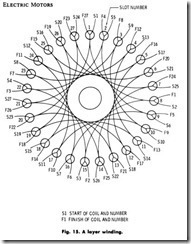
Layer winding is used where the coils have few turns of large wire and end room is limited, making it practically impossible to use for rewound coils. (Fig. 15). It will be almost impossible to use this method if the following equation is not satisfied:
Number of Poles x pitch + 1 = number of slots
For example, to determine whether a four-pole armature with 27 or 29 slots is suitable for this type of winding, substitute the proper values in the equation, (4 x 7) + 1 = 27 or 29. With a coil pitch of seven, it is evident that layer winding can be used in this case. The 27-slot armature is progressively connected and the 29-slot armature is retrogressively connected. Follow the procedure outlined below:
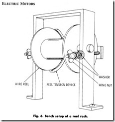
1. Set up the reel of wire, of proper size for the armature, on a reel rack with a suitable reel-tension device, Fig. 6.
2. Set the reel tension so that very little mechanical resistance is offered to a pull on the wire. This resistance will cause the reel to stop and prevent the wire from becoming uncoiled when no longer
pulled.
3. Shape the end turn of the first turn over the end of the armature, toward the shaft, to about the center of the space which all the end turns of the coil will occupy.
1. . The following end turns are laid on opposite sides alternately; the second turn is laid to the right of the first end turn, the third turn is laid to the left of the first end turn, the fourth is laid to the right, and the fifth is laid to the left. Proceed alternately in this manner until the entire coil is wound. Allow the wires to bunch up in the slots, but start to fan them out as close to the slot ends as possible.
5. Proceed in the same manner as outlined in 1, 2, 3 and 4 for each coil until the entire armature is wound.
6. Refer to the later part of this chapter for connections to the commutator .
IDENTIFYING THE COIL LEADS WHEN WINDING
Leads must be properly identified; otherwise making connections will be highly complex and, in some cases, practically impossible. Below are listed the methods of identification for the various conditions encountered.
1. For armatures with the same number of bars on the commutator as there are slots, no identification is necessary.
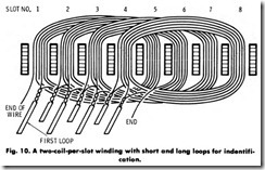
2. For armatures with twice as many bars on the commutator as there are slots, there will be two loops per slot. To distinguish between the first and second loops of each slot, the second loop is made longer than the first, or sleeving of two different colors is put on the Joops. Fig. 10. The sequence of color applied at the first slot must be carried out for every slot.
3. For armatures with three times as many bars on the commutator as there are slots, there will be three loops per slot. Use three dissimilar colors, one color for each loop of the slot. The sequence of color applied to the first slot must be carried out for every slot.
4. . When coils are wound with more than one wire in hand, as in a case where the number of commutator bars exceed the number of slots, use one sleeve of one color over all of the start leads and one sleeve of another color over all of the finish leads.
MACHINE WINDING
An armature-winding machine is used in production shops for wind ing small armatures. Machine winding is impractical for a shop which receives only a few small armatures to rewind. The machine consists of a drive motor mounted on a pedestal, a counting device, a hand wheel on the drive shaft for controlling the last few turns of a coil, holding clamps to fit various sizes of armatures, a foot lever in the pedestal for controlling the motor, wire-tension devices, and wire-spool holders.
FORM WINDING
Very often a rewinding job is made easier by preforming the coils and then placing them in slots. This may be done in various ways.
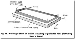
1. Drive finishing nails into a board, leaving the nails protected with sleeving, Fig. 16. Space the nails at intervals identical with the size and shape of the coil. The size of the coil is usually obtained from an old one at the time the machine is disassembled. If it cannot be ascertained in this manner, wind a single piece of wire in the slots, allowing sufficient slack for later installation without crowding. Twist the two ends of the wire together, remove from the slots and use for measuring the forming board. Fig. 16. After the required number of turns are wound on the form, tie it in several places and remove from the forming board.
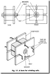
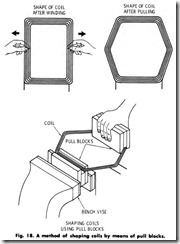
Use a block or blocks of fiber insulation or wood shaped to the proper size of the coil. Clamp two side pieces of fiber insulation to the sides of the block form to retain the winding on the form, while the winding takes place. The form is rotated on a spindle driven by a speed-controlled drive. Fig. 17. Wind the coil with the same number of turns and the same size of wire as the original coil. Obtain measurements as described in 1 above. Tie the coil in several places before removing it from the form. Coils may be shaped after winding by means of pull blocks. Fig. 18.
COIL WINDING MACHINE
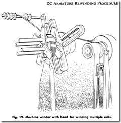
A coil-winding machine, Fig. 19, generally consists of a stand, an electrical motor drive, a gear reduction unit, a handwheel on the output shaft for controlling the last few turns of a coil on the winder head, a turns-counting device, an adjustable coil-forming winder head, and a foot control. The general procedure for winding a coil or coils on this type of machine is:
1 . Adjust the winder head to the size and shape of the coil required;
this is obtained from a coil removed from the armature in its entirety or from a wire loop adjus ted to the coil pitch and size of the core.
2 . Set up a reel of the proper wire size for the coil or coils on a reel rack with a suitable reel tension device on the floor.
3 . Set the reel-rack tension so that very little mechanical resistance is offered to a pull on the wire and so that when pulling is stopped, the reel will stop and thus prevent the wire from becoming uncoiled.
4. Attach the end of the winding wire to one of the winder head rod spools by looping the end once and giving the wire a couple of twists.
5. Start the motor by closing the motor-switch circuit.
6. Start the machine by depressing the foot pedal and control the starting speed with the left hand on the handwheel.
7 . Guide the wire onto the winder head with the right hand.
CAUTION: Protect the hand from the running wire by wearing a work glove or by using a folded piece of insulation held in the palm of the· hand. Do not try to hold back the machine by increasing the hand tension on the wire. Use the handwheel on the output shaft for this purpose. If the folded insulation is squeezed to cause tension, the running wire may heat up and ruin the insulation. Use the folded insulation in the hand to guide the wire only.
8 . Gradually let the coil winder attain the desired speed by relieving the pressure of the left hand on the hand wheel.
9. Observe the counting device occasionally to determine the number of turns of wire being put on the coil form.
1 0 . When the required number of turns have been wound onto the coil, release the foot pedal (by taking the foot pressure off of it) to stop the machine.
1 1 . Tie the coils with twine at the top and bottom (to prevent unraveling) and then remove from the form.
1 2 . Follow the procedure outline in the next heading for taping and insulating coils.
1 3 . Identify the start and finish of the coils with sleeving.
INSULATING COILS
Slots of large armatures and stators are generally open and the coils are usually completely taped. Cotton tape is often used for this purpose, with varnished cambric and mica preferred for large motors and special applications. In medium-sized motors, the slots are generally semi closed. The coils on such motors cannot be completely taped because the turns of the coil often must be fed into the slot one at a time. The part of the coil which is wrapped is that part which extends on either side of the slot. Methods are given below for taping and insulating coils when required.
1. Complete taping of a coil.
a. Start taping near the finish lead, making sure to engage the sleeving.
b. Continue around the coil, half-lapping each turn of tape over the preceding one until the start lead is reached.
c. Engage the sleeving of the start lead and continue to the start of the taping.
d. Fasten down the end of the wrapping with masking tape or twine.
2. Partial taping of a coil.
a. Tape the back end of the coil first and only that portion which will be outside the slots (this is determined by measurement of the slot length).
b. Half -lap each turn of tape over the preceding turn.
c. Secure the tape end with masking tape or twine.
d. Tape the front end by starting ahead of the start lead, at the
point where the coil enters the slot (this is determined by measurement of the slot length).
a. Half -lap each turn of tape over the preceding turn.
b. Engage the sleeving of the start lead and continue taping to the finish lead.
c. Engage the sleeving of the finish lead and continue to where the coil enters the slot.
h. Secure the tape end with masking tape or twine.
3. Varnish-insulating a coil. Refer to the procedures for reinsulating by applying insulating varnish. Normally, the insulated windings of a motor or generator require reinsulation when they appear dry, brittle, and faded. Reinsulation, in this case takes the form of revarnishing. For small motors and generators, use a synthetic varnish of the baking type. The windings of large units take black baking varnish of the asphalt type. While satisfactory for insulat ing windings in small motors and generators, hard varnish should not be used for large-unit windings because of the risk of damaging the winding beyond use when it is removed from the frame.
PLACING ARMATURE COILS IN SLOTS
The placement of preformed coils into the slots is dependent upon the type of slot. Care must be exercised so that conductors are not scraped, wrappings are not disturbed, and insulations are kept intact. Follow the outlined procedures for inserting the coils after the slots have been prepared with insulation.
Semiclosed Slots
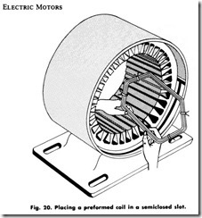
1. Spread or fan out the turns on one side of an untaped or partially taped coil. (Fig. 20).
2. Hold the coil at an angle and introduce the turns into the first slot,
one or a few at a time (depending on the space limitations of the slot opening) until all the turns are in the slot.
3. Place one coil side in all the slots as outlined in step 2 above. Do not insert the second coil side until every slot has one coil side placed.
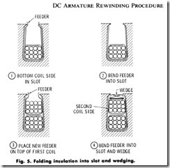
4. Place a strip of insulation in every slot on top of each inserted coil side. The strip should be 0.020 inch thick and 1/4 inch (6mm) wider and 1 inch (25mm) longer than the slot. Center it so that the width is evenly tucked around the coil side and extends 1/2 inch ( 12mm) on both ends. Another way is to bend the insulation feeder of every slot into the slot, one side overlapping the other. Fig. 5.
5. In the case where the slot insulation was bent and folded inward, place another slot feeder as shown in Fig. 5.
6. Place or insert the second side of a coil, fitting it on top of the first side of a coil, through the opening of the second feeder, insert
insulation, several slots away, depending on the coil pitch.
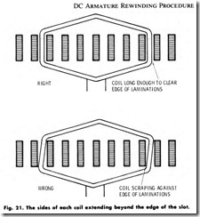
7. Make certain that each coil side extends beyond the slot at both ends and that they do not press against the iron core at the corners. Fig. 21.
8. Fold in the slot feeder as described in Fig. 5.
9. Wedge in the winding as described in Securing Windings in the Slots.
Open Slots
Completely taped coils are most often used in open slots although in some instances partially taped coils are used; which ones are used depends on the available space within the slot. After the armature has been properly insulated, place coils in the slots according to the following procedure.
1. Place one coil side in all the slots. Do not insert the second coil side until every slot has one coil side placed.
2. Place the second side of a coil, fitting it on top of the first side of a coil several slots away, depending on the coil pitch.
3. Make certain that each coil side extends beyond the slot at both ends and that they do not press against the iron core at the corners.
4. Wedge the windings as described earlier in the chapter.
