Block Diagram Representation
Complicated system may have several elements in cascade or in the feedback. It is useful to represent this kind of system in block diagram form. A single transfer function may be shown as a single block, where the input of the system x( s) entering the block diagram and after transformation leaves the block diagram as y( s).
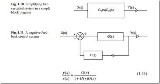
This is shown in Fig. 1.8, where G( s) is the transfer function. If two block dia- grams appear in cascade as shown in Fig. 1.9, the result is obtained by multiplying the two transfer functions together. This is shown in Fig. 1.10.
When two or more variables have to be added or subtracted, a circle is used to show this. The summation or subtraction is shown by + or − sign on the circle.
A feedback is obtained when the subtraction is performed. This is shown in Fig. 1.11.
For simple multivariable control system, principle of superposition can be used and a single output variable with respect to a single input variable can be studied. Any simple or complicated block diagram can be reduced to a single block. For example, the block diagram in Fig. 1.11 can be reduced to a single block as
A positive feedback is used as shown in Fig. 1.11. With positive feedback instead of negative sign; the reduction procedure is the same as before. The positive feed- back of Fig. 1.11 is reduced to a single block diagram as in Fig. 1.13.
The above procedure can be used for any complicated block diagram and helps to reduce it to a single block.


