NON REMOVABLE VALVE GUIDES
Most modern overhead valve engines do not have removable valve guides. Th e valves operate in guide holes bored directly in th e material of the cylinder head.
If the clearance becomes excessive, the usual method of rectifying it is to use the next oversize valve and ream the guide bore to fit. Valves with oversize stems are usually available in .003″ or
.005″, .015″ and .030″ oversizes.
If the wear is not excessive, it is possible to recondition both replaceable and non-replaceable guides by knurling their inside surfaces. This process raises ridges of metal on which the valve stem rides. The ridges also are very effective in retaining lubricant in the guides.
It is also possible in some engines to drill out the non-replaceable guide holes and press in stan dard type guides, but this is a highly skilled job as the drilling may go through into the water pas sages in the head. If this happens, it does not always mean scrapping the head, as it is some times possible to seal the new guide to the head. But great care and experience are needed, so this work should not be undertaken without careful considera tion of the possible consequences.
VALVE SPRING TESTING
Valves will not operate pr operly if their springs are weak. Full strength springs are essential if the valves are to follow their earns while elosing. If the springs are weak, the valves elose later than they should, the result being loss of power, over heated exhaust valves, and increased valve noise. Even slightly weak springs may cause trouble at maximum engine speed.
It is not good praetiee to do a valve job without testing the springs, because weak springs may be the real eause of the necessity for the valve job, in which ease, another valve job will be required long before it would otherwise be necessary.
For example, if a given spring calls for a pres sure of 125 pounds when compressed to 1W’ and is less than 112 pounds, a new spring should be installed.
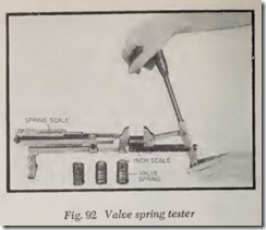
There are a number of tools on the market for measuring spring pressure. Figs. 92, 93, and 94 illustrate three of them. In Fig. 92, the valve spring is plaeed between the two jaws, and the handle is pushed forward until the ineh seale shows that the spring length has been reduced to 1W’. The spring scale should then register 125 pounds-in the ease of the spring just mentioned.
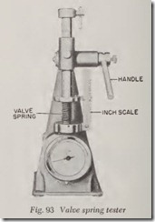
In the tool shown in Fig. 93, the valve spring is installed between the two plates. Then the handle is pressed down until the spring is compressed to the specified length. The pounds pressure exerted by the spring is registered on the dial.
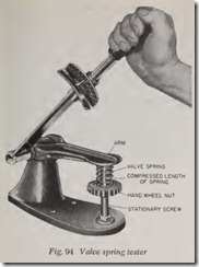
Fig. 94 shows a fixture which permits using a torque wrench to test the valve spring strength. The hand wheel is adjusted so that the distance from it to the top of the serew equals the specified compressed length of the valve spring. Then the valve spring is put in plaee and the handle pulled down until its arm contacts the top of the serew. Then the number of pounds pull on the torque wreneh is read.
When testing springs, be caref ul not to earn press them beyond the specified length as further compression may permanently wea ken them.
VALVE SPRING, REPLACE
A new spring can be installed without removing the cylinder head on all overhead valve engines as well as on some L-head engines.
If the coils on the spring are closer together at one end, be sure to install the spring so that this end is in the same position as on the other springs.
Overhead Valve Springs
On overhead valve engines remove the rocker arm cover. Before attempting to remove the spring the valve should be closed so that minimum com pression of the spring is necessary. The piston should also be at or near the top of its stroke to prevent the possibility of the valve falling down into the bore while the broken spring is being removed and a new one installed.
Loosen the locknut on the ball adjusting stud, and screw the stud upward so that the top of the push rod can be moved out of the rocker arm. The rocker arm can now be moved out of the way of the valve spring, either by tilting it upward or pushing it to one side.
Using a suitable valve spring compressor, remove the valve spring lock and spring. Then in stall the new spring. To hold the valve up while removing or replacing the spring, insert a bent rod through the spark plug hole, pressing its inner end against the head of the valve.
L-Head Valve Springs
On L-head engines whether or not a broken valve spring can be replaced without removing the cylinder head depends on whether enough clearance is available between valve stem and valve lifter to work the old spring out and work the new spring in. The valve is pushed up as far as it will go and if the lifter is adjustable, it is screwed down as far as possible to obtain maxi mum clearance between stem and lifter. If the lifter has a detachable guide, there is no problem. Just remove the guide and then there is ample room for removing and replacing the spring.
On a given L-head engine it is not easy to determine beforehand whether the spring can be removed without removing the head. But nothing is lost by trying. Before attempting to remove the spring, crank the engine until the valve is closed. Then compress the spring and remove the retainer lock and retainer.
If the valve moves upward when the spring compressor is used, remove a spark plug and hold the valve down on its seat with a small rod.
After the retainer has been removed, use a small screwdriver to hold the tip of the valve up while the lower end of the spring is started through the clearance space between the valve stem and the lifter. A broken spring, of course, should be easier to remove than a complete spring. Therefore, there is the chance that the broken spring can be removed but the new spring can’t be installed without removing the cylinder head.
VALVE GRINDING
It seems almost unnecessary to explain that the purpose of grinding valves is to cure valve leak age. Valve grinding smooths up the face of the valve seat and valve face so that the two re finished surfaces mate so perfectly that leakage is eliminated.
It is customary to use two specially designed electrically-driven grinding tools, one for the valve and the other for the seat.
Electric Valve Grinder
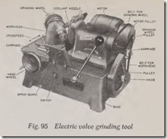
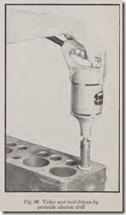
There arc two kinds of tools. One refaces the valve, Fig. 95, and the other refinishes the valve seat, Fig. 96. The valve seat refinis hing tool is equipped with a grinding wheel that has the same angle as the valve seat.
In the valve refinishing tool, Fig. 95, the face of the valve is parallel to the face of the grinding wheel. This means that the stem of a 45-degree angle valve makes a 45-degree angle with the face of the wheel.
Both the grinding wheel and the valve rotate. In the tool shown, the grinding wheel and its car riage can be moved right or left by swinging the lever. In this way the rim of the wheel is aligned with the face of the valve.
The workhead is mounted on a cross-feed car riage which can be moved toward the grinding wheel or away from it by turning the hand wheel. To grind a valve, the valve face is moved into light contact with the grinding wheel.
To sum up, the grinding wheel carriage can be moved left or right and the workhead can be moved at right angles to the carriage.
Electric Valve Seat Grinder
A grinding wheel operated by an electric drill is used to refacc valve seats. A steel cutter may be used except in the case of valve seat inserts which are too hard for the cutter to do a satisfactory job.
One such grinder has a concentric grinding wheel which contacts the seat all around its rim, Fig. 96. This design is often made so that the wheel vibrates or bounces off of the seat about once every revolution. The grinding wheel is lined up on the seat by means of a pilot which is in serted in the valve guide. Only a few seconds are required to reface a cast iron scat, a little more time is necessary for refacing the much harder valve seat inserts. This type tool is always used in conjunstion with a pilot inserted through the valve guide so that a concentric refinishing job will be obtained, Fig. 97.
Hand Grinding
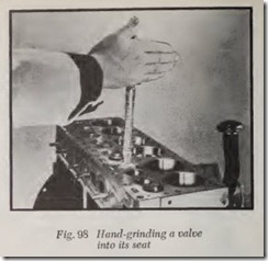
To hand-grind a valve into its seat, a thin coat ing of valve grinding compound is spread on the face of the valve. A common valve grinding tool, Fig. 98, has a rubber suction (vacuum) cup which is pressed against the valve and then it is rotated between the two hands while pressing down just enough to force the valve agains its seat. A light spring, just strong enough to lift the valve, should be placed under the head of the valve. After every few oscillations the spring is allowed to lift the valve and the valve is rotated through a part of a revolution. Then the valve is ground for a few more oscillations, and so on. About every minute the valve is removed and both the valve face and the seat are inspected. When the seat has been ground down so that bright metal shows all around its circumference, and when a similar band of smooth surface ap pears on the valve face, the valve may be con sidered finished.
Hand grinding is a slow, time-consuming job and the accuracy obtained is not likely to be as good as with suitable power tools, especially if the valve stem is somewhat loose in its guide.
After each valve is ground, both the valve and its scat should be carefully cleaned of abrasive with a rag moistened with gasoline or kerosene.
Valve Seat Widths
When grinding valve scats it is important to have the seat the correct width. If the scat is too narrow, it may wear unduly because it is not wide enough properly to resist the continual pounding against it. Also, an exhaust valve scat that is too narrow may overheat the valve because of in adequate contact area between valve and seat.
On the other hand, if the valve seat is too wide , the valve may not seat tightly . Other things being equal the wider the seat the m ore likely it is to leak.
The reason the valve with the wider seat is more likely to leak is that it has less pr essure per square inch to hold it down. If th e valve spring pull is 100 poun ds and the valve f ace area for the 1/16″ wid th were .293 square ineh, then the pres sure on the seat wou ld be 341 pounds per square inch. However, if th is seat wer e enlarged to a width of 3/16″, the pressure would be reduced to
114 pounds per square in ch beca use th e area would be three times as great for th e sam e pounds pressure of the spring.
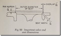
Therefore, for best valve service, the width of the seat should be neither too mueh nor too littl e. The recommendations of th e various car makers should be caref ully followed, bu t if in doubt as to what width is best, you can’t go wrong if you make the seat wid th 1/16”, Fig. 99. Note that this picture represents a typical va lve in a new engine.
The face of the valve should extend about 1/32″ beyond the face of the seat, Fig. 99. This over lapping is desirable so that the va lve face will have full contact with the seat. On the other hand, too much overlap invites overhea ting of the rim of the exhaust valve.
After a valve is ground, if its rim margin is less than 1/32″ thick, the valve should be discard ed because a thinner rim may become so hot that it will cause pre-ignition.
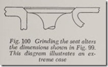
When a valve seat is gr ound, bo th the width of the seat and the outer diameter of th e seat ar e increased. Fig. 100 shows the outer diam eter of the scat has increased, the width of th e seat is greater, the rim of the valve no longer overlaps the outer circumference of the seat, th e valve has moved closer to its tappet.
Usually it is only necessary to remov e a f ew thousandths from the seat to smooth it up . In fact so little may be removed that scat width etc., ma y not be appreciably affected. On the oth er hand , if the seat is badly burned, it is necessary to grind off all the burned metal, in wh ich case, the dim en sions mentioned may be greatly increas ed as shown.
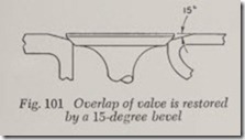
The outer diameter of the seat can be reduced by means of a 15-degree grinding wh eel, Fig. 101. Enough material is ground off the seat so that its outer diameter is reduced to what it was in a new engine and overlap is now correct. This operation also reduces the width of the seat.
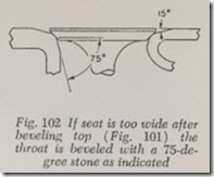
But if the seat is still too wide, its width should be reduced to the correct dimens ion with a 75-dcgree grinding wheel, Fig. 102.
Removing material from the top of the seat is ealled topping whil e removing it from the throat of the valve port is ealled throating. The wheel angles for toppin g usually are either 15 or 20 degrees and for throating 60 to 75 degrees.
When consid erable material is removed from the valve seat, the inner rim of the seat may extend down into the rough casting which forms the valve port . If this rim is uneven, the throating wheel should be used to make the rim perfectly eireular but in doing so be careful not to make the seat too narrow.
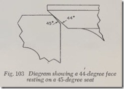
In some cases where exhaust valve burning is difficult to overcom e, it has been found very satis factory to mak e th e an gle of the valve faee to 1 degree flatter than the seat faee, Fig. 103. In other words, with a 45 degree seat, the angle of the valve face is mad e somewhere between 44 4 and 44 degrees. ( The angle between the valve faee and the seat is ealled the interference angle.) Thus th e valve seats tightly only at the outer edge of th e seat as shown. The narrow contact between valve and seat means that the unit pressure is very high between the narrow contacting surfaces, henee the tight seating. Also because of the high eontaet pr essure any particles lodging on faee or seat are likely to be quiekly pulverized and blown away.
The use of an interference angle naturally reduces the contact area between valve face and seat and therefore it might be assumed that the flow of heat from the hot exhaust valve would be throttled and exhaust temperature would be dan gerously increased. Nevertheless, it is apparent th at with a narrow contaet the pressure with which the valve face pushes against the seat is so high and the contact is so intimate that heat flows from valve to seat very readily whereas with valves an d seat having exactly the same angle the f ull width eontaet means that the intensity of pr essure between them is relatively low and there fore the contact is less intimate. Hence, heat trans fer from valve to seat is not as good as might otherwise be expected.
It should also be noted that exhaust valves usually cause no trouble until they begin to leak. lien ee, sinee the narrow contaet suppresses leak age the valve job is likely to last longer. And with leakage almost entirely absent, the actual exhaust valve temperature may be less with a narrow con tact th an with a wider one which permits some leakage right from the start. This leakage may not be enough to be noticed in the operation of the engin e but it may be sufficient to elevate the valve temperature to a point which hastens the destruc tion of the valve job.
The interference angle, as it is ealled, is ob tained by adjusting the workhead on the valve grinding tool to somewhere between 44 and 44;14 degrees (in the case of a 45-degree seat). For a 30- degree seat, the valve face angle should be 29 to 29% degrees.
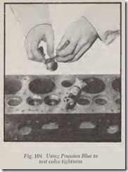
After the valve grinding job is finished, it is de sirable to determine how tightly the valve fits into its seat. Two simple methods are as follows: ( 1) Spread a thin eoating of Prussian Blue evenly on the valve face, Fig. 104. Put the valve on its seat and rotate it a few times. If the valve is tight, there should be a continuous band of blue on the seat. ( 2) Make a few peneil marks aeross the width of the valve face. The marks should be fairly evenly spaced around the circumference. Put the valve on its seat and rotate it a few times. Remove the valve and inspeet the pencil marks. If all of them show signs of being rubbed by the seat, the job is satisfactory.
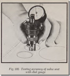
After refinishing valve seats, the accuracy of the job may be checked with a dial gauge, Fig. 105. The gauge is mounted in a fixture which includes a pilot which goes into the valve guide. An arm on the gauge is brought into contact with the valve seat and is moved around the full eireumferenee of the seat. If the pointer on the gauge varies more than .002″ the seat is not sufficiently ac curate. For a really good job the variation should be .001″ or less.
