HIGH PERFORMANCE PUSH RODS AND ROCKER ARMS
Push Rods
Push rods can deflect under load and this must be taken into account when special replacement units are being considered. Most high perfor mance push rods are made of a chrome-moly steel tube, which is both light in weight and rigid, so that it offers good high speed operating character istics. It should be pointed out that if a push rod should bend or whip in operation, it will affect the valve operation, altering the timing and possibly affecting the ability of the valve to seal the cylin der properly.
Rocker Arms
Rocker arms serve a dual purpose. They receive the motion of the cam at one end and multiply it by the ratio of the rocker arm while transferring it to the valve at the other end. The ratio of the
rocker arm is the distance from the center of the push rod contact point to the center of the rocker shaft, divided into the distance from the center of the valve stem to the center of the rocker shaft. (Measurements are taken to the center of the stud hole when the rocker arm is mounted on a stud.) This ratio is usually about 1.5 to 1.
Rocker arms may or may not be adjustable, depending on the design of camshaft and the type of lifter used. Most high performance camshafts use adjustable rocker arms and a solid (non hydraulic) lifter cam to maintain proper valve lash at high engine speeds.
For high engine speeds, pressed in rocker studs should be replaced by threaded ones.
Some ultra-high performance rocker arms are made of light weight, high strength aluminum and have a needle bearing roller to contact the valve stem. This reduces the friction between rocker arm and valve stem to a negligible quantity, and at the same time reduces the side force on the valve stem resulting from the arc in which the rocker arm operates. This in turn reduces friction between valve stem and guide, and wear on the guide and stem.
When modifying an engine for high perfor mance, it is important to remember that rocker arm geometry, or rocker arm-to-valve stem rela tionship, must not be changed. Incorrect geometry can result in increased side loads on the valve, rapid wear of the valve guides and stems, and other problems.
ROCKER ARM SERVICE
After removing the roc. cr arm cover, if the rocker anns are found to be heavily sludged, stuck or damaged, the assembly should be removed for cleaning and opening up of oil passages. If none of these conditions is apparent, run the engine with the rocker arm cover off. While the engine is running, check the rocker arms and shafts to see that oil is being distributed to all the shaft bear ings and to the outer end of the arms. Correct lubrication of these parts is indicated when oil drips from the bearing edge of each rocker arm and spreads over the push rod ends.
Oil failing to show at these points is usually caused by dirt in the oil feed pipe, in which case it should be removed and cleaned, preferably by blowing out with compressed air.
Too much oil flowing is a definite indication of worn rocker arms and shafts, which calls for re placement of these parts.
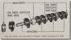
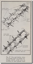
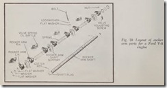
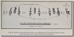
Before removing or disassembling a rocker arm assembly, note carefully the arrangement of the parts and look for any identifying marks which indicate their location. Figs. 36 to 40 illustrate the parts that make up a representative group of rocker arm assemblies.
The rocker arm assembly should always be removed befor e removing the cylinder head. The first step is to remove the rocker arm cover plate. Then remove the push rod cover (if used). Detach the oil connections at the rocker arm shafts or supports. Then unscrew the bolts holding the supports and lift off the rocker arm assembly. Remove the push rods before removing the head and replace them after installing the head to avoid aecidentally damaging them.
In disassembling the rocker arms from their hafts, it is most important to place the parts along the back of the work bench in exactly the same relationship they assume when on the engine, otherwise there may be difficulty in as sembling them properly. This is particularly im portant because rocker arms are not all alike; some are at right angles to the rocker shafts and others may be a few degrees more or less than a right angle.
When assembling rocker arms to shafts, squirt oil on the shafts to provide initial lubrication when the engine is started.
ROCKER ARM COVER
Remove the nuts from the top of the rocker arm cover and lift it off. Clean the cover both inside and outside. Also clean the rocker arm mecha nism, and the strainer in the oil line to the rockers (if one is present).
When replacing rocker arm covers always use a new gasket and torque the bolts or cap screws to proper specifications to prevent oil leakage.
L-HEAD VALVE COVER
Before removing the covers, wipe away all dirt and scratch a small identifying mark on each cover so that it can readily be ‘returned to its proper place. Remove the nuts or screws with washers and take off the covers. Thoroughly clean the covers with gasoline or other cleaning fluid and wipe dry. As a precaution against subsequent leakage, remove the old gasket, being careful to scrape all remnants from the cover and engine. Remove dirt, oil and sludge from the valve cham ber and the valve mechanism by either brushing with gasoline or by the use of cleaning equipment. If the bottom of the valve chamber is open to the crankcase, stuff the openings with rags before cleaning the valve mechanism.
CYLINDER HEAD, REMOVE
Except Corvair, Jeep, Pontiac Tempest OHC & Volkswagen Engines
A cylinder head is fastened to the cylinder block by studs and nuts or by cap screws. To remove the head, the nuts or cap screws are taken out and the head is lifted off. Do not remove a cylinder head when the engine is hot because cylinder head warpage may result.
Before removing a cylinder head, it is necessary to remove any parts that are in the way and to detach any connections between the head and the rest of the car.
Disconnect the starter cable at the battery to prevent accidental shorts.
Disconnect the hose between cylinder head and radiator. Before doing so, drain enough liquid from the cooling system to prevent leakage when the hose connections are loosened. If the liquid contains anti-freeze, drain it into a clean pail so that it can be put back into the system after the repair work is done.
Detach the temperature gauge wire or tube.
Remove high tension cables from spark plugs.
Remove carburetor air cleaner.
If water pump is attached to cylinder head, remove fan belt.
Remove or detach any other item which may int erfere with taking off the cylinder head.
The preceding remarks apply generally to both L-head and overhead valve engines. However, it should be noted that there is some additional preliminary work to be done on overhead valve engines because the intake and exhaust manifolds are attached to the head instead of to the block as on the L-head.
On overhead valve engines any tubing or rods which interfere with the removal of the head must be disconnected as follows:
Detach vacuum advanee tube at carburetor.
Detach windshield wiper tube at the intake manifold or detach the tube running from the intake manifold to the vacuum side of the fuel pump (if so equipped).
If the coil is attached to the cylinder head, detach the high-tension cable running from coil to distributor at the distributor.
Detach the fuel line at the earburetor. Detach the throttle rod at the carburetor.
Remove the carburetor and intake manifold as a unit.
Detach the exhaust manifold from the cylinder head or disconnect the exhaust pipe from the exhaust manifold-whichever is easier.
Remove the rocker arm cover. Remove the rocker arm assemblies. Remove the push rod cover.
Pull the long push rods up through the head as they are likely to be damaged if the head is removed first.
Remove the cylinder head nuts or cap screws with a socket wrench. If cap screws are used, carefully note their length as they are removed. If there arc some long and some short ones, be sure to remember which holes the long ones came from so that when the head is replaced the long ones will be installed in the long holes. If a long bolt is installed in a short hole and turned up tight, the cylinder block may be broken beyond repair, in which case a new one will be required. However, if you forget which holes are the long ones, mea sure the depth of all holes with any handy rod-a pencil will do. If still in doubt, insert the long bolts in the holes that are longest and turn them up gently. Then if a bolt refuses to go in all the way (without using force) it is in the wrong hole.
Once the cylinder head nuts or cap screws have been removed, the head is ready to be lifted off. If the head is large, such as a straight eight, two men may be required. If it does not come off readily, jolt it crosswise and lengthwise with a rawhide hammer. If it still sticks, crank the engine with the throttle open and ignition off to loosen the head by the force of compression pressure. Before doing this, however, install spark plugs in the end eylinders to hold the compression, and install a pair of nuts or cap screws. Draw them down finger tight and then back off about two turns. Crank the engine with the starter to see if the head will break loose.
If this does not work, install two eye bolts in the head and apply a chain hoist or a crane just as though you were going to life the engine out of the car.
If the block is equipped with studs, the sticking may be due to corrosion between the studs and head. In this case, squirt some special penetrating oil made for the purpose on the studs so that it will seep down and loosen up the corrosion. A really stubborn case of corrosion may require the removal of the stud; there are a number of stud removers on the market.
Some combination of these methods should loosen any cast iron head and most aluminum heads. However, in the case of some of the older engines equipped with aluminum heads, if the head is badly corroded, no available force will remove it. Therefore, it may be necessary to de molish the head and remove it piece by piece.
CYLINDER HEAD, INSTALL
Except Corvair, Jeep, Pontia c Tempest OHC & Volkswagen Engines
Handle the head carefully . Do not allow it to strike any open valves as this may bend them. Before replacing the head be sure th e gasket surfaces of the head and bloek are perfe ctly clean, otherwise the gasket may leak when the head is installed. Also be sure that there is no carbon or dirt in the cylinder head bolt holes, or any foreign matter in the bolt holes in the block. If there is, blow them out with compressed air. Dirt in the holes may prevent drawing the bolts up tight.
On some engines, the bolt holes in th e block extend into the water space, in which case the end of the bolt should be coated with wh ite lead or sealing compound to prevent leakage.
If there are any burrs around the edges of the bolt holes in the block it is advisable to remove them with a medium file as these burrs may prevent the gasket from fitting tightly. In fact, all burrs on both the head and block should be removed.
It should be noted that the cylinder h ead gasket may have bolt or stud holes which are slightly enlarged on the under face to take care of burrs. If the holes are slightly larger on one side, this side should contact the block. Some gaskets are marked “Top” or have lettering on th e top side. Always install a new gasket as the old one may leak even though it appears to be perfect.
Place the gasket on the cylinder block to be certain that it fits. If all bolt holes and water passage holes do not line up, turn the gasket upside down or end for end and inspcet it again. Some gaskets are marked “Front” at the front end; if so, be sure to install it this way.
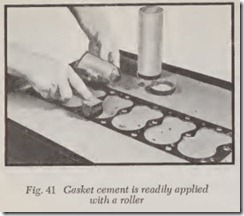
Apply a eoat of gasket eement to both sides of the gasket, using a roller as shown in Fig. 41. Place gasket on a piece of heavy paper. Coat one side. Allow eement to dry tacky. Then turn gasket over and eoat other side. If a roller is not avail able, use a brush. In the ease of some Buick models the gasket is coated with a laequer when it is made, and no additional eement should be used.
On cars that use eylinder head eap serews in stead of studs it is desirable (but not absolutely necessary) to install two “pilot” studs in the bloek to guide the head into place. These studs are made by sawing the heads off of two spare cylin der head cap serews. Screw them lightly into bolt holes at opposite ends of the block. If serewed in too tight it will be diffieult to remove them later. After these studs are installed, put the gasket in plaee and then install th e head.
Lubricate the threads on the eap serews and the bosses on the eylinder head. Install the eap screws and turn them until they are nearly tight. Then remove the two pilot studs and install cap screws
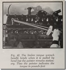
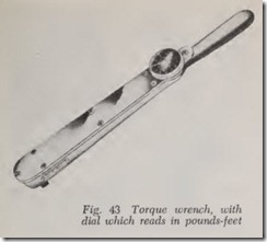
in these holes. Use a torque wreneh, Figs. 42 and 43, to draw the bolts up tight. It is important to tighten the bolts in proper sequenee and to tighten them just the right amount in order to prevent distortion of the cylinder block or eylinder head, as well as to insure a tight gasket.
Usually the seale on the torque wreneh reads in pounds-feet of torque. But if the wreneh reads aeeording to some arbitrary scale, it is eustomary for the wreneh manufacturer to supply instruc tions with the tool so that the wreneh scale read ings can be translated into pounds-feet. The term “pounds-feet” simply means the force in pounds applied to the wreneh handle at a radius of one foot. Note that the correet term is pounds-feet and not foot-pounds, although foot-pounds is almost universally used.
All car manufacturers specify the pounds-feet torque which should be used in tightening their eylinder heads and also the sequenee in whieh final tightening should be done.
Be eareful to tighten the eylinder head cap serews or stud nuts exactly to the ear maker’s specifications. Tightening them a little more or less than the specified amount is objectionable beeause “more” may eause distortion and “less” may permit gasket leakage.
If the eylinder bloek is equipped with studs, put the gasket on the block, install the eylinder head and lubricate the threads on the studs. Put on the nuts and draw them up until they are nearly tight. Then finish the job with the torque wreneh as previously deseribed.
After the head is installed, attach all other parts whieh have been removed from the engine exeept the valve covers or the roeker arm eover, which ever is used.
Be sure to fill the radiator.
Start the engine and allow it to run at a fast idle for at least 15 minutes; half an hour is better. After the engine has been run until thoroughly warm, and if it has a cast iron head, tighten all eap serews or stud nuts but do not use more than the speeified torque. If the engine has an alumi num head, shut the engine off after it has been warmed up and tighten the cap serews and studnuts to the specified torque after engine has cooled.
On overhead valve engines with mechanical valve lifters, always check the valve operating clearance after installing the cylinder head.
CORVAIR CYLINDER HEADS
The procedure for removing a Corvair cylinder head differs a great deal from that of a conven tional car, chiefly because the engine is enclosed in metal shields and shrouds and because the engine must be lowered to provide access to the head for its removal. Because of its relative com plexity, a step-by-step procedure is herewith given for 1960–64 models. On 1965 models it is not necessary to lower the engine.
Removing Left Bank Head
1. Drain crankcase oil. This is necessary be cause when the push rod drain tubes are removed, their entrance holes in the cylinder block will be open and the oil may spill out as the engine is being manipulated.
2. Disconnect battery cables, engine ground
connection, radio ground strap, left side carburetor cross-shaft support from carbu retor, and fuel line at carburetor.
3. Remove carburetor intake hose, carburetor accelerator return spring, and disconnect accelerator rod from carburetor.
4. Remove carburetor and the long stud from the carburetor mounting.
5. Remove wires and spark plugs.
6. Loosen (do not remove yet) all engine side shield retaining screws. Remove screw from engine side shield under carbur etor (at tached to cylinder head) and then remove engine side shield.
7. Remove oil cooler; this allows engine rear shroud freedom of movement during cylinder head removal.
8. Raise car on hoist and attach a suitable lift ing fixture to the power train (engine, trans mission and rear axle assembly).
9. Remove both engine side seal retainers and engine rear seal retainers.
10. Remove engine rear center shield and seal assembly.
11. Remove lower engine shroud.
12. Remove exhaust pipe-to-manifold nuts.
13. Open french locks on exhaust manifold and remove holding clamp nuts.
14. Remove exhaust manifold.
15. Remove engine rear mounting cotter pin, nut and washer from below body rear mounting bracket.
16. Remove rocker arm cover while h olding a pan below to catch oil draining from cylinder head.
17. Remove rocker arms, push rods and push rod guides.
18. Remove rocker arm studs, washer s and “0” rings from head.
19. Remove “0” rings from bottom of push rod drain tubes with a pair of hooked tweezers.
20. Remove retaining nuts and washers retaining head.
21. Carefully lower engine assembly approxi mately 3″ to clear eylinder head earburetor flange.
22. Remove eylinder head from erankease studs.
Removing Right Bank Head
Removal and installation of the right bank head is essentially the same as the left head, exeept the eoil, oil pressure and oil temperature sending units must be disconn ected. Also remove the ehoke heat pipe and choke fresh air pipe from the exhaust manifold.
Replacing Corvair Cylinder Head
The proeedure for replaeing the head is aeeom plished by reversing the removal operations. However, in order that the reader may gain some knowledge of the unique eonstruction of this engine, a sequenee of operations for replaeing the head when the engine is removed from the chassis is hereby outlined:
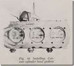
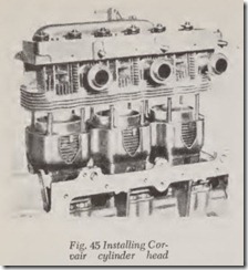
1. Be sure all eylinder head gaskets are in the eombustion ehambers, as shown in Fig. 44. Then install head, Fig. 45.
2. Install six Hat washers and nuts on long studs, adjacent to intake manifold. .
3. Install six new “0” rings in counterbore of cylinder head, Fig. 46. Coat rings with Lubriplate and rocker stud bore with anti seize compound. Then install rocker arm studs.
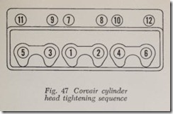
4. Tighten nuts and rocker studs in the sequence shown in Fig. 47.
5. Lightly lubricate valve lifters and install in their proper bores.
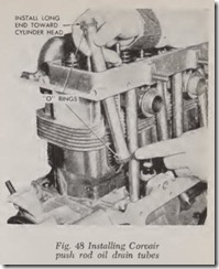
6. Install push rod oil drain tubes, Fig. 48. Oil the “0” rings and push in place at lifter bore at crankcase and cylinder head.
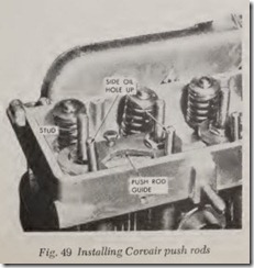
7. Install push rods with side oil hole up into valve rocker socket, Fig. 49.
8. Install push rod guides over rocker studs and push rods and tighten nuts.
9. Install rocker arms, balls, and nuts. Adjust valve lash as outlined previously after install ing distributor.
Replacing Jeep Overhead Camshaft Cyl. Head
1. To remove head with timing chain cover in stalled, first take off rocker arm cover.
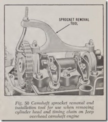
2. Install camshaft sprocket removal and instal lation tool on rocker arm cover studs, Fig. 50. Fasten with rocker arm cover nuts. Install hook of removal tool in the sprocket ·and tighten the nut to relieve the tension on the camshaft.
3. Remove fuel pump eccentric from camshaft sprocket.
4. Pull forward on camshaft sprocket to remove it from pilot on camshaft. With sprocket still engaged in timing chain, release tension on tool by loosening nut. Gently allow sprocket to rest on bosses in timing chain cover. Caution: Do not turn over engine when sprocket is removed from camshaft and is resting on bosses in cover. This will severely damage cover. Do not attempt to remove
camshaft sprocket from timing chain since this will upset the valve timing .
5. Disconnect lubrication t ube from head and block.
6. Remove cylinder head bolts.
7. Lift off head assembly.
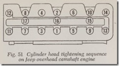
8. Reverse the removal proce dure to install the head. Position the all-metal hea d gasket on the block so that the coolant ports and vent ports are properly aligned. Use no sealer or other compound on the gasket. When head is installed, tighten it down in the sequence sho·wn in Fig. 51.
Replac ing Pontiac Tempest Overhead Camshaft Cylinder Head
1. Drain cooling system and remove air clean er.
2. Disconnect accelerator pedal cable at bell crank on manifold and fuel and vacuum lines at carburetor.
3. Disconnect exhaust pipe at manifold flange, then remove manifold bolts and clamps. Re move manifolds and carburetor as an as sembly.
4. Remove rocker arm cover.
5. Remove timing belt upper front cover mount ing support bracket and rear lower cover.
6. Disconnect spark plug wires.
7. Remove rocker arms and hydrau lic valve lash adjusters. Store rocker arms and lash adjusters so they can be replace d in exactly the same location.
8. Remove head bolts and lift off hea d . Noti ce that head bolts are of two differen t lengths. When inserted in proper holes all bolts will project an equal distance from head. Do not use sealer of any kind on threads.
9. Reverse the removal procedure to install the head.
VOLKSWAGEN CYLIN DER HEADS 1200, 1300 and 1967-681500
To remove Volkswagen cylinder heads, it is first necessary to remove the engine from the car. Th e procedure is as follows:
1. Disconnect battery ground strap.
2. On early models, turn off fuel tap. On later models pull off fuel hose and clip it.
3. Remove carburetor air cleaner.
4. Remove engine rear cover plate.
5. Disconnect wires from generator, ignition coil and oil pressure switch.
6. Disconnect accelerator cable from carburetor.
7. Loosen and turn distributor to allow vacuum unit to clear rear cover plate when engine is being removed.
8. Raise vehicle at least three feet off the ground.
9. Disconn ect both heater control cables and loosen flexible heater pipes from engine.
10. Disconnect fuel hose from engine.
11. Remove nuts from both engine lower mount-ing bolts.
12. Pull accelerator cable from guide tube.
13. Place a roller jack under engine.
14. While holding the two upper engine mount ing bolts, have an assistant remove the nuts.
15. Raise jack to support engine.
16. Withdraw engine far enough to allow clutch release plate to clear main drive shaft. Then lower jack and tilt rear of engine downward until it can be completely removed.
1965-1966 1500 and All1600 Models
1. Disconnect battery ground strap.
2. Remove air cleaner.
3. Remove cables from generator, coil, oil pres sure switch and automatic choke.
4. Detach accelerator cable at connecting link.
5. Remove oil dipstick and take off rubber boot betw een oil filler and body.
6. Loosen clip on bellows at cooling air intake housing and pull off bellows.
7. Remove rear engine support.
8. Raise and support vehicle on stands.
9. Disconnect flexible pipes between engine and warm air mixing boxes.
10. Disconn ect heater flap cables.
11. Take warm air hose from carburetor preheater off engine.
12. Pull off fuel hose at front engine cover plate and seal it with a suitable plug.
13. Remove two lower engine mounting nuts.
14. Support engine with roller jack.
15. Hold two upper engine mounting bolts while an assistant removes nuts.
16. Pull engine back slightly until release plate clears main drive shaft.
17. Lower engine, being sure that clutch release plate or main drive shaft are not damaged.
Installation, All Models
When installing the engine, take care to prevent damage to the flywheel gland nut needle bearing and clutch release bearing. To ease entering the main drive shaft into the clutch plate and gland
nut needle bearing, engage a transmission gear to keep the mainshaft from turning and rotate the engine by the fan belt as required.
When installing the engine, first install the mounting bolts into the transmission case flange. Then press the engine against the flange, being sure it seats properly around the flange before installing the nuts. Tighten the upper nuts finger tight first, then the lower nuts. Final tightening should be done in the same order.
To remove a cylinder head, with the engine out of the car:
1. Remove hoses between fan housing and heat exchangers.
2. Remove front and rear engine cover plates.
3. Remove muffler.
4. Remove fan belt.
5. Pull off coil-to-distributor cable.
6. Remove fan housing with generator.
7. Remove intake manifold with pre-heatingpipe.
8. Remove both heat exchangers.
9. Disassemble and remove cylinder deflector plates.
10. Remove cylinder head cover.
11. Remove rocker shafts.
12. Remove push rods.
13. Remove cylinder heads.
Cylinder Head
Each pair of cylinders has one detachable cylin der head. The head has cooling fins and shrunk-in valve seat inserts and valve guides. No gasket is used between the joining faces of the cylinder and head. Gaskets are used, however, between the flanges of the cylinder and cylinder head to pre vent leakage of combustion gases.
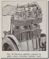
NOTE. If a cylinder head is to be removed, a suitable cylinder retainer can be made locally to prevent the cylinders from being pulled off acci dentally, and to eliminate the danger of dirt enter ing the crankshaft, Fig. 52.
When installing heads, the following points should be observed:
1. Check· heads for cracks in combustion chamber and exhaust ports. Cracked heads must be replaced.
2. Check spark plug threads in heads. If neces sary, install Heli-Coil threaded inserts. (These are a proprietary method of restoring stripped or damaged female threads in a casting.)
3. There is no gasket between upper edge of cylinder and cylinder head.
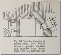
4. On 1200, 1300 and 1967-69 1500 models, fit new sealing ring between cylinder shoulder and cylinder head, Fig. 53.
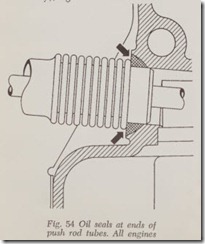
5. On all engines, when installing cylinder head, make sure that oil seals at ends of push rod tubes are properly seated, Fig. 54.
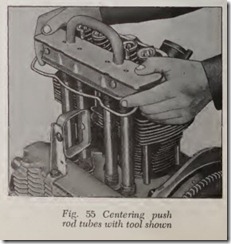
6. Push rod tubes can best be centered by using a centering tool of the type shown (made locally), Fig. 55.
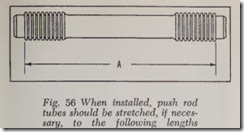
7. Tum the tubes so the seam is facing upwards.
For perfect sealing, used tubes must be stretched to the correct length before they are installed. This operation must be carried out very carefully to avoid cracking the tubes, Fig. 56.
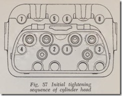
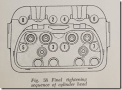
8. Coat attaching nuts with graphite paste ana screw them down until resistance can be felt. Then tighten initially with a torque wrench to 7 ft-lbs in the sequence shown, Fig. 57. Final tightening should be made in the sequence shown in Fig. 58 to the specified torque.
