TIMING BELT AND CAMSHAFT SPROCKE REPLACE
Pontiac Tempest Overhead Camshaft Engine
1. Remove timing belt top front cover.
2. Remove sprocket to camshaft retaining bolt.
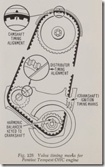
For ease of reassembly, index timing marks shown in Fig. 128.
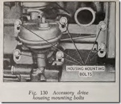
3. Loosen six accessory drive to engine block mounting bolts, Fig. 130.
4. Remove timing belt from camshaft sprocket.
Caution: Do not use tools of any type, other than hands, to pry on the timing belt during belt removal or replacement or during other service operations.
5. Remove camshaft sprocket.
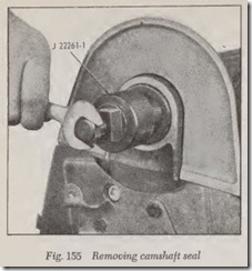
If necessary to replace camshaft seal, reinstall sprocket bolt. Thread a tool of the type shown, Fig. 155, into camshaft seal. Tighten center bolt on tool until seal is extracted.
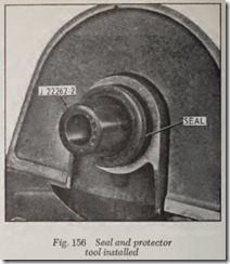
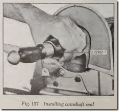
Install a suitable seal protector and pilot, Fig. 156, on end of camshaft. Slide seal over tool, then drive it in place, Fig. 157.
CAMSHAFT, REPLACE
Except Jeep & Pontiac Tempest Overhead Camshaft Engine
The removal of the camshaft may be required for a variety of reasons, such as:
1. If new mushroom type valve tappets must be installed, the camshaft must be taken out unless the tappets are mounted in detachable guides.
2. If the camshaft gear is worn excessively and is pressed on to the camshaft so tightly that it cannot be removed by a puller, the cam shaft must be removed and the gear pressed off by means of an arbor press.
3. If new camshaft bearings are requir ed, obviously the camshaft must be taken out to replace the bearings.
4. The camshaft may be worn, bent, twisted or broken.
It may be quicker or even necessary to remove the engine from the chassis to get the cam.sha t out. Indeed, it is necessary to remove the engme If camshaft bearings are to be replaced. However, if the camshaft is to be removed with the engine in the car, the radiator, and usually the grille has to be taken off, as well as the fuel pump, distributor and/or oil pump. The valve tappets must either be removed or lifted up and secured out of the way.
On overhead valve engines with barrel-type tappets, lift them out before removing the cam shaft.
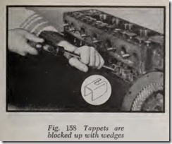
On engines with mushroom tappets, the tappets can be held up out of the way by various methods without removing the valves. These methods can be used whether the tappets are mushroom or barrel type. Fig. 158 shows a method suggested by Studebaker wherein special U-shaped wedges are made from sheet steel. The right end is slotted at the top so that it slips under the head of the tappet adjusting screw. When the wedge is driven into place it raises the tappet out of the way of the cams. It is not necessary to remove the cylinder head.
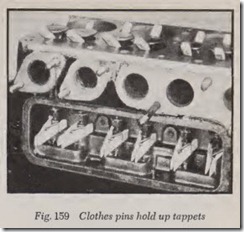
If the cylinder head is removed, the valves may be blocked open as shown in Fig. 159. Then the tappets are lifted up and held there with clothes pins.
On almost all automobile engines the oil pump and/or the distributor are driven by a gear on the camshaft. Usually this gear drive interferes with the removal of the camshaft which means that the distributor or the oil pump or both must be re moved before the camshaft can be taken out.
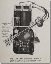
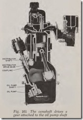
On most cars the oil pump and distributor are driven from opposite ends of the same shaft, Figs. 160 and 161. Distributor and oil pump shafts are separate and are connected together b a tongu.e and slot construction. In Fig. 160 the dnve gear IS attached to the distributor while in Fig. 161 it is on the oil pump shaft. Therefore in Fig. 160 the distributor must be removed in order to allow the camshaft to be taken out while in Fig. 161 the oil pump must be removed before camshaft removal.
The reason why this drive gear gets in the way is easy to explain. The gear on the camshaft which rotates the drive gear must be no greater in diameter than the eamshaft bearings, otherwise it will not go through the bearings. Therefore, the teeth of the drive gear whieh meshes with it obviously must extend inward toward the earn shaft 7 ” or so and therefore will interfere with cams and journals whenever the camshaft is re moved or replaced.
Before attempting the removal of the camshaft, some further explanation of oil pump and distrib utor drives is desirable. In all cases, remove the distributor first. If the drive gear is attached to the distributor shaft, Fig. 160, it is obvious that re moval of the oil p1,1mp will not be necessary. On the other hand, if the drive gear is on the oil pump shaft, the oil pump must be removed.
In Fig. 161, the drive gear is fastened to the oil pump shaft and the oil pump is readily accessible because it is mounted on the outside of the crank ease.
After carrying out all the directions in the pre ceding paragraphs the camshaft should eome out readily. The camshaft should be handled with care as its finely finished surfaces are rather easily damaged. Be careful not to drop the camshaft, as it is easily bent.
Inspection
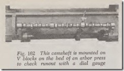
For best valve action the camshaft should not be out of true more than .002″. If the deviation is more than .002″ the camshaft should be straight ened or replaced. The check for this condition is by the use of V blocks mounted on the bed of a wide arbor press, Fig. 162, or on a flat plate. Mount the camshaft end journals on the V blocks and then check the intermediate journals with a dial indi cator. Check these journals by rotating the cam shaft a full revolution. The high reading of the indicator indicates the high point of the shaft. Chalk mark this point and apply pressure by means of the arbor press to straighten the shaft. Press and re-check until the shaft is less than .002″ out of true. When pressing, avoid damage to the journal by inserting a brass or copper plate or a block of hard wood between the journal and the head of the arbor press.
Excessive camshaft run-out may cause m1ssm g at low speed by preventing full closing of some of the valves because the heel of the cam interf eres.
Installation
Before installing the camshaft, coat the cams and bearing journals with engine oil and insert th e camshaft carefully.
Mesh the timing gears according to th e marks on them or mesh the timing chain according to instructions previously given.
The next job is to time the distribu tor. Turn the crankshaft until it is in the correct position for breaker point opening on No. 1 cylinde r, just the same as for checking spark timing.
Then take the distributor in your hand and turn the rotor until it points to the segment which connects with No. 1 spark plug cable. Tum th e distributor shaft slightly until the breaker points arc just ready to open.
Install the distributor on the engine and check spark timing to be sure that the wo rk has been properly done. Also check valve timing, if in doubt as to whether the timing gears or chain have been properly meshed.
Defore permanently installing the distributor, if the oil pump has not been removed, turn its drive shaft so that its tongue and groove coupling will mesh with the distributor shaft when the points are just ready to open to fire No. 1cylinder.
If the oil pump was removed, install it after the distributor has been installed, being careful to mesh the tongue and groove coupling by turning the oil pump shaft until the meshing of the cou pling takes place.
If the camshaft gear is a press fit on the camshaft, as in the case of Corvair and Chevrolet 6- cylinder engines, the camshaft must be removed to install a new camshaft gear. Use an arbor press, Fig. 163, to press the gear off. The gear should be mounted on the support sleeve shown. Press the new gear on the shaft by means of the arbor press.
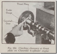
When the camshaft gear is designed to be a tight press fit on the camshaft, a new thrust plate (if used) should be put on the shaft before press ing the gear on with an arbor press and remember that there must be a little clearance between the hub of the gear and the thrust plate. The clear ance should be somewhere between a free fit as a minimum and .003″ as a maximum. When the gear has been pressed on nearly all the way, check the clearance between thrust plate and gear until it is .003″ or less but also make sure that the clearance is enough so that the thrust plate can be rotated freely on the shaft, Fig. 164.
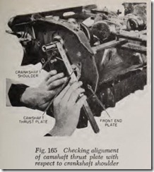
On Chevrolet 6-cylindcr engines, before install ing the camshaft, check the alignment of the camshaft thrust plate with the shoulder on the crankshaft, Fig. 165. The alignment should also be checked in case new gaskets are required between the front end plate and the cylinder block in order to cure oil leakage at this point. In either case, proceed as follows:
In assembling the front end plate to the cylin der block, first use two gaskets and hold the plate with three screws. Then place a new camshaft thrust plate over the camshaft hole in the end plate. Using a steel scale as a straight edge, place it across the face of the thrust plate and note whether it is flush with the crankshaft thrust shoulder. If not, either add one gasket or remove one gasket so that the scale will be practically flush with the shoulder.
