TIMING GEARS, REPLACE
The camshaft gear on automobile engines is usually made of a highly compressed fibrous com position material and ther ef ore is called a fibre or composition gear. Some cars, however, have aluminum gears. The cranksh aft gear is always steel.
The fibre gear provid es a quieter drive than a metal gear. The fibre gear wears somewhat faster than the steel crankshaft gear. Therefore, if the gears are noisy it may be sufficient to install only a camshaft gear. In some cases camshaft gears with teeth of oversize thickness are available. Thus, this so-called oversize gear compensates for the wear of the teeth on the camshaft gear, assuming it is not replaced.
Clearance between teeth of a new pair of gears when installed, Fig. 145, should be somewhere between .002″ and .006″. The same clearance limits arc desirable if an oversize camshaft gear is mated with a worn crankshaft gear.
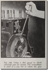
However, it should not be forgotten that a gear with a slight wobble may be noisy. Therefore, if tooth clearance is satisfactory, check the gears for runout before removing them, Fig. 146. If runout
is more than .004”, check for burrs on the gear hub and camshaft where the gear is mounted. If the runout cannot be brought below .004″, it is desirable to install a new gear. The runout of the crankshaft gear should not be more than .003″.
Removal
If the eamshaft gear is not retained by a nut or bolt in the end of the shaft, it is a safe assumption that the gear is a press fit and that the power of an arbor press will be necessary to remove the gear. This means that the camshaft must be removed from the car.
If the camshaft gear is bolted on it is readily removed by taking off the bolts or screws hold ing it.
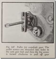
If the eamshaft gear is retained by a nut on the end of the shaft, either a lifter bar may be used to remove it, Fig. 136, if it is not on too tight. Other wise use a puller of which there arc various types. Fig. 147 shows one type. Another type is shown in Fig.139.
In Fig. 147, there are two threaded holes in the hub of the gear. The puller screws are inserted in these holes to the full depth of the hub, otherwise the screw threads may be damaged or stripped. Then turn the center screw of the puller to remove the gear.
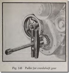
Fig. 148 shows a puller ready to remove the crankshaft gear. It is the same tool used in Fig. 147 for cam gear removal.
Installation
If a pusher tool is not available the new crank shaft gear can be installed with a soft hammer or hammer and hollow drift, such as a piece of pipe.After the camshaft and crankshaft gears have been reinstalled on the engine, it is a good plan to check the gears for runout with a dial indicator, Fig.146.
Camshaft gear run-out of more than .004″ is not desirable. The figure is .003″ for the crankshaft gear. To check either gear for runout place the tip of the dial gauge on contact with the rim of the gear as shown and rotate the gear through one revolution. High and low readings for the cam shaft gear should not vary by more than .004″ for the cam gear and .003″ for the crank gear.
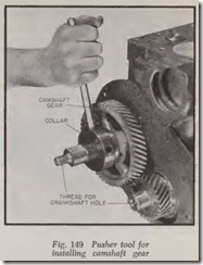
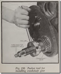
Fig. 149 shows a tool for installing the cam gear while Fig. 150 shows the same tool ready to install the crankshaft gear. Looking at the two pictures it will be seen that both ends of the center screw are threaded. The screw end visible in Fig. 150 is threaded into the hole in the camshaft, Fig. 149, while the screw visible in Fig. 149 is threaded into the hole in the crankshaft, Fig. 150. In either case the gear is installed by turning the collar clock wise.
TIMING CHAIN AND SPROCKETS, REPLACE
Except Jeep Overhead Camshaft Engine
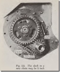
When both the chain and the sprockets are new there should be a slight sag or slack as shown by the broken white line, Fig. 151, if the chain is pushed as indicated by the white arrow. Note that this test is made on the slack side of the chain and that the other side of the chain is under tension because the rotation of the crankshaft sprocket pulls on the chain to rotate the camshaft sprocket. The motion of the sprockets and chain is shown by the white arrows. A chain that is too tight will be noisy.
It is desirable to put on a new chain when wear allows the chain to sag more than , when pressed inward on the slack side.
The camshaft and crankshaft sprockets should also be examined for wear and replaced if visibly worn or scored. Badly worn sprockets will shorten the life of a new chain and may cause the drive to become objectionably noisy.
To remove the chain it is always necessary to remove the camshaft sprocket and sometimes it is necessary to remove both sprockets and the chain as a unit.
The method of removing the sprockets and replacing them is similar to removing and replac ing the timing gears as previously explained.
Jeep Overhead Camshaft Engine
Removal
1. Remove timing chain cover.
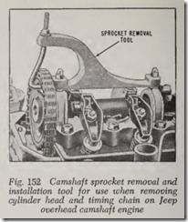
2. Install tool shown in Fig. 152 on rocker arm cover studs. Install hook of tool in camshaft sprocket and tighten nut to relieve tension on camshaft.
3. Remove fuel pump eccentric from sprocket.
Pull forward on sprocket to remove it from camshaft pilot.
4. Release hook of tool and slide sprocket off camshaft.
5. Remove chain tensioner spring to release tension on tensioner blade. Remove blade and spring from lower tensioner mounting stud.
Inspect Chain & Sprockets
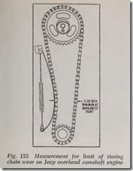
Check the chain for excessive wear or stre’ tch When the chain is installed with th e chain ten sioner in place, measure the distance between the chain sides at the narrowest point , Fig. 153. If the distance is less than the required m inimum as shown, the chain must be replaced. If sprockets appear to be excessively worn, replace th em also.
Timing Chain Tensioner
This device maintains a constant pressure against the chain to compensa te for nor mal stretch and wear of the chain. Check the contact face of the tensioner blade to make sure the rubber facing material is not worn through . Replace if badly worn. Check the tensioner spring to m ake sure it is not distorted or elongated.
Install Chain & Sprockets
1. Tum over engine until air st arts to blow from No. 1 spark plug port to in dicate that No. 1 piston is on the compression stroke.
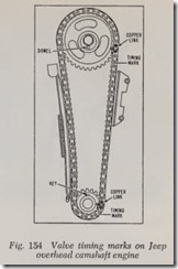
2. Continue to turn over engine until keyways in crankshaft are in the 12 o’clock position, which will indicate that No. 1 piston is at top dead center, Fig. 154.
3. Temporarily install camshaf t sprocket and turn camshaft until nose of No. 1 cam and dowel hole on camshaft are pointing down ward at the 6 o’clock position.
4. Remove camshaft sprocket.
5. Install key in crankshaft keyway nearest cylinder block.
6. Install tool shown in Fig. 152.
7. Position sprockets in opposite ends of chain so that keyway in crankshaf t sprocket is up and dowel of camshaft is down. Position parts so that copper links of th e chain are aligned with timing marks on sprockets
8. Lift up assembled chain and sprockets and slide crankshaft sprocket on crankshaft so that the sprocket is fully seated.
9. Engage hook of tool, Fig. 152, on sprocket and tighten nut to tension the chain and pull the mounting hole of the sprocket into alignment with the pilot on end of camshaft.
10. Push sprocket into camshaft pilot so that dowel engages hole in flange on camshaft. This may require slight rotation of crank shaft to secure perfect alignment.
11. Install fuel pump eccentric on camshaft sprocket.
12. Release tension of special ,tool, Fig. 152, and remove tool from rocker arm cover studs.

