This chapter examines Ohm’s law and how it is applied to a circuit. Some of the concepts were introduced in previous chapters.
Electric circuits
As stated earlier, current flows from a point with an excess of electrons to a point with a deficiency of electrons. The path that the current follows is called an electric circuit. All electric circuits consist of a voltage source, a load, and a conductor. The volt- age source establishes a difference of potential that forces the current to flow. The source can be a bat- tery, a generator, or another of the devices described in Chapter 12: Voltage. The load consists of some type of resistance to current flow. The resistance may be high or low, depending on the purpose of the circuit. The current in the circuit flows through a conductor from the source to the load. The conductor must give up electrons easily. Copper is used for most conductors.
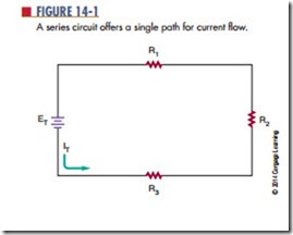
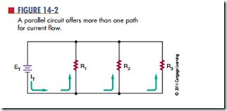
The path the electric current takes to the load may be through any of three types of circuits: a series circuit, a parallel circuit, or a series-parallel circuit. A series circuit (Figure 14-1) offers a single continuous path for the current flow, going from the source to the load. A parallel circuit (Figure 14-2) offers more than one path for current flow. It allows the source to apply voltage to more than one load. It also allows several
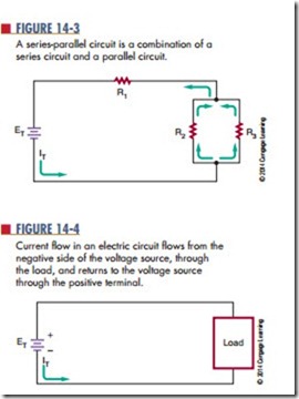
sources to be connected to a single load. A series- parallel circuit (Figure 14-3) is a combination of the series and parallel circuits.
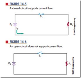
Current in an electric circuit flows from the negative side of the voltage source through the load to the positive side of the voltage source (Figure 14-4). As long as the path is not broken, it is a closed circuit and current flows (Figure 14-5). However, if the path is broken, it is an open circuit and no current can flow (Figure 14-6).
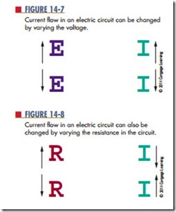
Changing either the voltage applied to the circuit or the resistance in the circuit can vary the current flow in an electric circuit. The current changes in exact proportion to the change in the voltage or resistance. If the voltage is increased, the current also increases. If the voltage is decreased, the current also decreases (Figure 14-7). On the other hand, if the resistance is increased, the current decreases (Figure 14-8).
Questions
1. What are the three basic parts of an electric circuit?
2. Define the following:
a. Series circuit
b. Parallel circuit
c. Series-parallel circuit
3. Draw a diagram of a circuit showing how current would flow through the circuit. (Use arrows to indicate current flow.)
4. What is the difference between an open circuit and a closed circuit?
5. What happens to the current in an electric circuit when the voltage is increased? When it is decreased? When the resistance is increased? When it is decreased?
