FORD ESC SYSTEM
Electronic Spark Control System
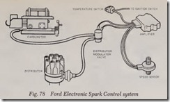
This system, Fig. 78, reduces the exhaust emis sions of an engine by providing vacuum spark advance only at speeds above 24 to 33 mph (de pending on the engine application). It consists of a speed sensor, an electronic amplifier, an outside air temperature switch and a vacuum control valve. The vacuum control valve is inserted be tween the carburetor vacuum advance port and the distributor primary advance connection. This valve is normally open, but when energized elec trically by the electronic amplifier it closes to cut off vacuum to the primary vacuum advance unit on the distributor thus preventing vacuum spark advance. The temperature switch, which is mount ed in either the right or left A-pillar, senses outside air temperature. A temperature below 49 degrees F. will cause the switch contacts to open, thereby de-energizing the vacuum valve and allowing normal vacuum advance at all speeds. A temperature of 60 degrees plus or minus 5 degrees F. causes the contacts to close, thereby cutting off vacuum to the advance side of the distributor at speeds below 24 to 33 mph. On deceleration the vacuum advance cut-out speed is approximately 18 mph.
On some applications the vacuum hose connec tions between the carburetor and distributor may route through a PVS valve. This valve serves as a by-pass or safety override switch. When the coolant temperature reaches 230 degrees F., mani fold vacuum is applied directly to the primary (advance) side of the distributor advancing the timing and thereby lowering operating tempera ture.
FORD HIGH SPEED EGR MODULATOR SUB-SYSTEM
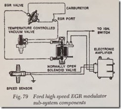
The high speed EGR modulator sub-system used on some V-8 engines, Fig. 79, is basically the same in operation as the ESC system described previously. This system cuts off exhaust gas re circulation :Bow by stopping vacuum :Bow from the EGR port to the EGR valve at speeds above 64 mph, in turn improving driveability.
The vacuum solenoid valve installed in the vacuum line is normally open (not energized), allowing vacuum :Bow from the EGR port to the EGR valve. The EGR system remains functional when the valve is not energized.
The speed sensor driven by the speedometer cable, produces an electric signal directly pro portional to vehicle road speed, signalling the am plifier to energize the vacuum solenoid valve at which time the electronic module receives the signal from the speed sensor and amplifies it to provide a usable signal to the vacuum solenoid valve.
When the vehicle speed exceeds approximately 64 mph (trigger speed of the amplifier) the circuit to the ignition switch is completed and the normal ly open vacuum solenoid valve is energized. The plunger moves upwards and shuts off the EGR port vacuum and the vent at the bottom of the vacuum valve is opened, bleeding vacuum from the EGR valve and hose. Spring force closes the EGR valve which remains non functional until the vacuum solenoid valve is de-energized, at speeds below approximately 64 mph.
NOTE: There is a continuous internal vacuum bleed provided by the vent at the top of EGR valve. Whether the valve is in a closed or open position, this vent purges the vacuum supply hose from carburetor of any gasoline vapor.
FORD TRS SYSTEM
Transmission Regulated Spark Control System
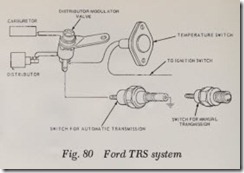
This system, Fig. 80, reduces the exhaust emis sions of an engine by providing vacuum spark advance only in high gear. It consists of a vacuum control valve, an outside air temperature switch, and a transmission switch. The vacuum control valve is inserted between the carburetor vacuum advance port and the distributor primary advance connection. This valve is normally open, but when energized electrically by the transmission switch it closes to cut off vacuum to the primary vacuum advance unit on the distributor thus preventing vacuum spark advance. The temperature switch which is mounted in either the right or left A-pil lar, senses outside air temperature. A temperature below 49 degrees F. will cause the switch contacts to open, thereby de-energizing the vacuum valve and allowing normal vacuum advance in all gears. A temperature of 60 degrees plus or minus 5 degrees F. causes the contacts to close, thereby cutting off vacuum to the advance side of the distributor in all but high gear.
FORD TRS +1
Transmission Regulated Spark + 1
The TRS +1 system, Fig. 81, consists of two separate vacuum control systems, that are electri cally controlled by input information from a manual transmission gear selector switch, and an outside
ambient air temperature switch. The TRS function of the TRS +1system is identical to the function performed by the 1972 TRS system. The plus 1 system of the TRS +1, controls the selection of the carburetor vacuum source for the vehicle EGR system. The EGR vacuum supply source can be either carburetor spark port, or carburetor EGR port depending upon the manual transmission gear
selected, and the outside ambient air temperature.
FORD SPARK DELAY VALVE
This unit is used in conjunction with some of the other Ford systems. Its purpose is to further re duce emissions by delaying the spark advance during rapid acceleration and by cutting off ad vance immedi:=ttely upon deceleration.
This plastic disc-shaped valve is installed in the carburetor vacuum line at the distributor advance diaphragm. It is a one way valve and will not operate if installed backwards. The back side of the valve must be toward the carburetor. This valve cannot be repaired or checked for proper operation. However, this valve can be checked for proper operation on 1975 vehicles.
NOTE: On all systems which employ the dual diaphragm distributor the line which has high vacuum at idle (normal operating temperature) is connected to the secondary (retard) side of the distributor vacuum advance unit. This is the con nection closest to the distributor cap.
FORD EGR SYSTEM
Exhaust Gas Recirculation
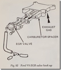
In this system the exhaust gases are metered through the EGR valve to a passage in the car buretor spacer to dilute the air fuel mixture en tering the combustion chambers. Dilution of the incoming mixture lowers peak flame temperatures during combustion and thus limits the formation of nitrogen oxides ( NOx).
Most eight cylinder engines use the “Spacer Entry” EGR System which has the EGR valve mounted on the rear of the carburetor spacer, Fig.82.
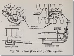
The exhaust gases are taken from a drilled pas sage in the exhaust crossover of the intake mani fold. The exhaust gas is then routed through a metered EGR valve to a passage in the carburetor spacer and fed into the primary bore. Some 1974 eight cylinder engines use the “Floor Entry” EGR system, which has the EGR valve mounted on the rear of the intake manifold. The EGR valve con trols the exhaust gases that enter specially cast passages in the manifold from the exhaust cross over passage. When the valve opens, the exhaust crossover is then opened to the two drilled pas sages in the floor of the intake manifold riser under the carburetor, Fig. 83.
On six cylinder engines, the EGR system is basically the same as the Spacer Entry EGR Systern except that exhaust gas is routed directly from the exhaust manifold.
Two variables control the operation of the EGR system, 1) engine coolant temperature and 2) car buretor vacuum. When engine coolant tempera ture is below the specified level the EGR system is locked out by a temperature controlled vacuum switch. This vacuum switch is installed in series with the EGR valve. This valve receives vacuum from a port in the carburetor body. When the valve is closed due to lower coolant temperature, no vacuum is applied to the EGR valve and no exhaust gas is fed to the air-fuel mixture. When the engine coolant temperature reaches the speci fied level, the valve opens allowing vacuum to be applied to the EGR valve. Exhaust gas is then fed to the air-fuel mixture.The second factor controlling EGR operation is carburetor vacuum. The location of the EGR port in the carburetor determines at what point vac uum is sent to the EGR valve. Vacuum should be fed to the EGR vacuum control valve when the primary throttle plate reaches a position corre sponding to a road speed of approximately 20 mph under light acceleration.
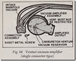
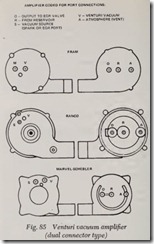
A Venturi Vacuum Amplifier, Figs. 84 and 85 used in 1974-77, uses a weak venturi-vacuum signal to produce a strong intake manifold vacuum to operate the EGR valve, thereby achieving an
accurate, repeatable and almost exact proportion between venturi airflow and EGR flow. This as sists in controlling oxides of nitrogen with minimal sacrifice in driveability.
There are three types of EGR valves, the poppet type, modulating type and the tapered stem type, Fig. 86.
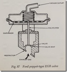
The poppet type valve, Fig. 87, consists of springloaded diaphragm, and a valve stem and valve operating in an enclosed valve body. At ap proximately 3 inch Hg of vacuum , the valve begins to open . The valve stem is pulled forward unseat ing the valve and allowin g the exhaust gas to flow into the valve chamber. Venturi vacuum will then pull the gas from the chamber into the air-fuel flow and then into the combu stion chambers. Once the valve has been unseate d the only means of limiting exhaust gas flow is the size of the flow restrictor placed in the inlet port of the valve body. The size of the restrictor will vary according to engine applicition.
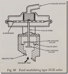
On the modulating type valve, Fig. 88, an addi tional disc has been added to the valve stem be low the main valve. The modulating valve operates exactly like the poppet valve when vacuum is be tween approximately 3 in. Hg. and 10.5 in. Hg.
When vacuum reaches approximately 10.5 inches, the lower disc (high vacuum flow restrictor) ap proaches the shoulders of the valve seat and re stricts the flow of exhaust gas. The purpose of the modulation of gas flow is to improve driveability on certain engine models.
NOTE: The EGR valve and vacuum control valve cannot be repaired and must be replaced if dam aged.
EGR Back Pressure Transducer
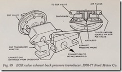
Used on some 1976 EGR systems, the back pres sure transducer is connected to an adapter be tween the EGR valve and intake manifold. The transducer modulates EGR flow by varying vac uum signal to EGR valve according to exhaust back pressure. Exhaust back pressure is sensed in pressure cavity of transducer spacer, Fig. 89.
Cold Start Cycle (CSC)
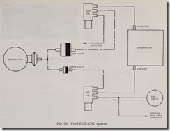
The EGR/CSC system regulates both distribu tor advance and EGR valve operation according to coolant temperature by sequentially switching vac uum signals. The major system components are: a 95° F. EGR-PVS (Ported Vacuum Switch) valve, a SDV (Spark Delay Valve) and a vacuum check valve, Fig. 90.
When engine coolant temperature is below 82°F., the EGR-PVS valve admits carburetor EGR port vacuum (at about 2500 RPM) directly to the distributor advance diaphragm, through the one way check valve. At the same time, the EGR-PVS valve shuts off carburetor EGR vacuum to the EGR valve and transmission diaphragm.
When engine coolant temperature is 95° F. and above, the EGR-PVS valve is actuated and directs carburetor EGR vacuum to the EGR valve and transmission diaphragm instead of the distributor. At temperatures between 82° and 95° F., the EGR PVS valve may be open, closed or in mid position.
The Spark Delay Valve ( SDV) delays carburetor vacuum to the distributor advance by re stricting the vacuum signal through the SDV for a predetermined time. During normal acceleration, little or no vacuum is admitted to the distributor advance diaphragm until acceleration is completed and engine coolant temperature is 95° F. or higher.
The check valve blocks off vacuum signal from the SDV to the EGR-PVS valve so that carburetor spark vacuum will not be dissipated when the EGR-PVS valve is actuated above 95° F.
The 235° F. PVS valve which is not part of the EGR-PVS system is connected to the distributor vacuum advance to prevent engine overheating while idling.
Cold Start Spark Advance (CSSA}
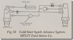
Used on some 1975-77 engines, this system, Fig.91, is added to the distributor control to provide manifold vacuum when engine coolant is below 125° F. by providing vacuum from the intake manifold, through the Distributor Retard Control Valve (DRCV), the CSSA PVS and to the dis tributor. At 125° F. and above, the vacuum flows from the carburetor spark port, through the cool ing PVS, the SDV, the CSSA PVS and to the dis tributor. Above 235° F., the vacuum flows through the SDV and CSSA PVS to the distributor. If en gine overheats at idle, increased vacuum will flow to the distributor to increase engine speed. When engine coolant temperature decreases, spark ad vance will be controlled by the carburetor spark port.
Dual Signal Spark Advance System (OSSA)
1975-76
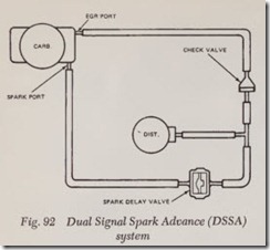
This system uses a spark delay valve ( SDV) and a one way check valve to provide improved spark and EGR performance during mild acceleration, Fig. 92. The check valve prevents spark port vac uum from reaching EGR and causing excessive EGR flow. The valve also prevents EGR port vac uum from diluting spark port vacuum which could result in improper spark advance. The SDV per mits application of full EGR vacuum to distributor vacuum advance during mild acceleration. During cruise conditions, EGR port vacuum is applied to EGR valve and spark port vacuum is applied to distributor vacuum advance.
DUAL-AREA DIAPHRAGM
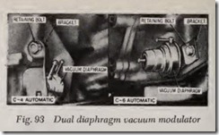
On 1973-77 vehicles, new dual-area diaphragms are used, Fig. 93. These diaphragms offset effects of engines using the EGR system and equipped with automatic transmissions. The new diaphragms permit vehicles to function with satisfactory shift spacing and shift feel.
To test, remove the vacuum diaphragm and test unit using an outside vacuum source. Set regulator on tester to 18 in. Hg. with end of vacuum hose blocked off then connect vacuum hose to vacuum diaphragm unit. If unit does not hold 18 in. Hg. reading, the diaphragm is leaking and must be replaced.
FORD DECEL VALVE
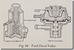
This valve, Fig. 94, used on the 1600cc, 2000cc, 2300cc and 2800cc engines, is mounted on the in take manifold adjacent to the carburetor and meters an additional amount of fuel and air dur ing engine deceleration periods. This additional fuel and air, together with engine modifications, permits more complete combustion with the re sultant being lower levels of exhaust emissions. During engine deceleration, manifold vacuum forces the diaphragm assembly against the spring in the decel valve, which in turn raises the decel valve (open position). With the valve open, exist ing manifold vacuum pulls a metered amount of fuel and air from the carburetor, which travels through the decel valve body assembly into the intake manifold. The decel valve remains open and continues to feed additional air and fuel for a specified time.
NOTE: On 1975-76 V6 Mustang models, the fuel decel system is controlled by vehicle speed through a transmission mounted switch. This switch prevents the system from operating during deceleration at speeds below 11 mph. On 1977 Mustang models with air conditioning, the fuel decel system is designed to operate only when the air conditioner is operating.
FORD DVB SYSTEM
Delay Vacuum By-Pass System
1973
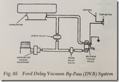
This system is used to by-pass spark delay valve (SDV) at temperatures below 49° F. The system incorporates two components of TRS system (am bient temperature switch and electrically operated vacuum control solenoid valve) and a check valve. The DVB system does not operate at temperatures above 65° F., thus the normal function of SDV will not be effected in warm weather, Fig. 95.
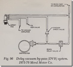
1975-76
This system allows full spark port vacuum to distributor vacuum advance below PVS opening temperature. The system uses a check valve, spark delay valve ( SDV) and 4 port PVS, Fig. 96. Above PVS opening temperature top two ports of PVS close, routing spark port vacuum signal through spark delay valve.
