Comparison of Results and Design Procedure
The choice of a motor for specific application depends on the priority placed on certain criteria, including the speed of response, stiffness to external torque, size, capital cost, running cost, reliability, and availability. The main object of this section is to establish a comparison of speed of response and effect of external torque, so that a designer is able to choose a specific motor to meet the dynamic performance requirements. The time response of a servo motor may be split into two parts.
1. The dynamic settling time in the linear mode, where the motor is operating within its limit condition. This implies that the operating conditions and the change in the variables involved is small, so they operate in a linear fashion as described by the mathematical model of the motor in previous chapters. Although it will not be rigorous, the dynamic settling time due to the inertia of the rotor ( tr1) will be separated from the dynamic settling time due to load inertia referred to the motor shaft ( tr2) for case of comparison.
2. The saturated settling time, where the motor is operating at its limit conditions.
This implies that the motor is drawing its maximum current and, therefore, pro- viding a constant torque for the initial part of a large change from steady state. The static settling time is a function of the required velocity variation in addition to the motor and load inertia.
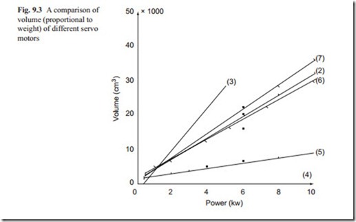
Figure 9.3 shows the variation of the sizes of motors for various types with respect to the power rating. It can be seen that the hydraulic motors have the lowest volume for a given power. This does not include the power pack requirements. Also the straight line indicates that the smallest hydraulic motor was capable of producing up to 10 kW power. This may be a disadvantage for hydraulic motors. The rare earth magnet DC motor produces the highest power for a given size in electrical motors. Again this does not include the weight of the power unit which should not be too large. It follows with printed or brushless DC servo motors. Then the induction AC servo motors have a comparable size to power ratio with brushless DC servo motors
and it seems that ceramic magnet DC servo motors have a higher size to power ratio than induction AC servo motors. But the power unit of AC induction servo motors have a larger unit with complex circuitry. The stepping motors are competing with other types of servo motors at low power range but at high power requirements, they are not very efficient. At very low power requirements, all servo motors have similar power to weight ratio and in this range the speed of response and stiffness to external torque become more important.
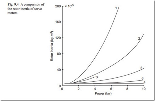
The speed of response strongly depends on the inertia of servo systems. It is use- ful to compare the inertia of the motor without any inertia referred to motor shaft. This is shown in Fig. 9.4. It can be seen that hydraulic motors have the lowest inertia for a given power. The brushless DC motors having lower inertia than other electric motors, and they are a good replacement for hydraulic motors as speed of response is concerned because lower inertia means the possibility of fast response. Stepping servo motors are only available at low power range and their inertia is higher than hydraulic and brushless and rare earth magnet DC motors. AC induction motors have low inertia at lower power range and the inertia increases rapidly as the power rating is increased. Ceramic magnet DC servo motors have similar inertia to other motors at low power range but increases rapidly as the power rating increases. It should be noted that in order to keep similarity, all motors up to the velocity of 1,500 rpm are compared in this section. Because as rotating velocity is increased, the inertia reduces but the maximum torque also reduces. This is because of design of motors. As rotating speed increases, the inertia reduces which means that greater power can be transmitted at higher velocity and at lower maximum torque.
The data presented in Figs. 9.3 and 9.4 is information obtained from a number of manufactures. The reader must keep an eye on the new development in this area and try to fit the information available in the above two mentioned diagrams.
In order to differentiate the effect of load inertia on the performance, the dynamic and saturated settling time are first obtained without any additional load inertia. In other words, first the response of the motor to large step input is studied and in this exercise it is assumed that the motor produces its maximum torque. This assumption is only valid when the maximum torque is used for a short period of time to avoid overheating in the circuitry.
The overall settling time of a servo motor with rotor inertia of ( Ir) and load inertia of ( Il) and velocity change of ( ωc) can be approximated as
tr2 Dynamic settling time due to a unit load inertia (s/(kg m ) ts1 Saturated settling time due to the rotor inertia and unit change in velocity (s/ (rad/s))
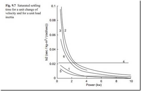
ts2 Saturated settling time due to a unit of load inertia and a unit change in velocity (s/(kg m2)/(rad/s) ωc velocity variation (rad/s)
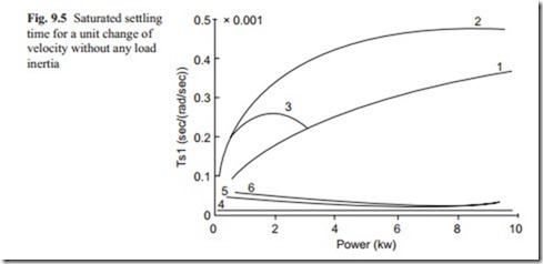
A simulation using the mathematical model presented in previous chapters is used to find the dynamic settling time of different types of servo motors. The dynamic settling time of servo motors without and load inertia is greatly influenced by the maximum torque availability of the motor and its rotor inertia. The saturated settling time of servo motors without any load inertia due to a unit change in angular velocity is approximated by
where Tm is the maximum torque of the motor and Ir is the inertia of the rotor. The above equation is derived by writing the Newton’s second law of motion and solv- ing the resulting equation for a unit velocity change.
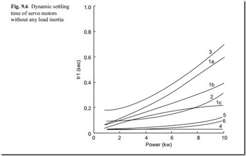
Figure 9.5 shows the saturated settling time of servo motors and Fig. 9.6 shows the corresponding dynamic settling time. It can be seen that the hydraulic motors give the lowest dynamic and saturated settling time compared with electric motors. At low power range, the electric motors are a good replacement for hydraulic motors.
The rare earth magnet and printed DC motors having low inertia have the fastest response time and then it follows by ceramic magnet DC motors, stepping motors, and induction AC servo motors.
Figure 9.6 shows that the hydraulic motors have the fastest dynamic response. The rare earth magnet and printed DC servo motors have a slightly larger settling time but they are competing well with hydraulic motors. The dynamic settling time also depends on the power unit used. It can be seen that PWM drive for DC motors produces a competitive response with hydraulic and brushless DC servo motors. The thyristor controlled DC servo motors have larger response time. The AC induction servo motors having a lower inertia even though have lower maximum torque compared with DC motors, have become good competitively for DC servo motors.
The stepping servo motors have the largest settling time at all power ranges. The stepping motors operating on the principle of magnetic pull inherently oscillatory and the controller must take this into account.
The approximate saturated settling time due to additional load inertia is similar to that for motor inertia, that is,
The above equation can be calculated for a unit load inertia and a unit velocity change. This gives the eq. (9.3) a generality for all types of servo motors and can be used in eq. (9.1) to obtain the total settling time for a given application.
Figure 9.7 shows this settling for a unit load inertia and for a unit of velocity change.
In Fig. 9.7 the saturated settling time of electrical AC induction, stepping and rare earth magnet DC motors are very large at low power rating. This means that a unit load inertia is very large compared to the inertia of the rotor. Hydraulic motor has an average saturated settling time slightly larger than rare earth magnet and ceramic magnet DC servo motors. At high power range electrical motors have the lowest saturated settling time. This means electrical motors must be matched to the load inertia referred to motor shaft.
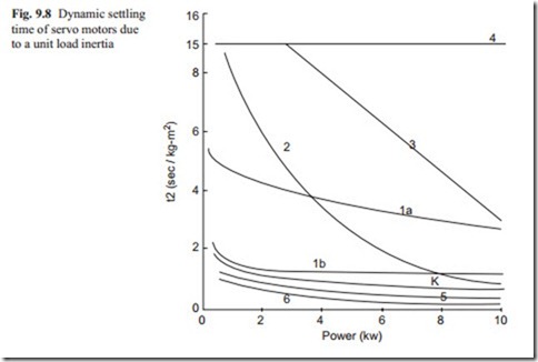
The dynamic settling time due to the load inertia is greatly influenced by the maximum torque capability of the motor. A series of simulations were carried out to obtain the dynamic settling time for all types of servo motors at different load
inertias, and the results were averaged and scaled for a unit load inertia. Figure 9.8 shows the results, and it can be seen that the hydraulic motor has the largest dynamic settling time. This is mainly due to the fact that because the maximum torque of the hydraulic motor is much smaller than electric motors and also the inertia of the hydraulic motor is much smaller that electric motors. It is also more sensitive to load inertia. The dynamic settling time of the stepping motor is larger than other electrical motors due to its sensitivity to load inertia. DC motors have the smallest dynamic and saturated settling time due to their capability of producing large torque for a short period of time.
The dynamic and saturated settling time of electrical motors due to load inertia reduces as the power rating of the motor increases, because higher power motor are capable of higher torque. As stated previously, the single hydraulic motor covered the range up to 10 kW power range and, therefore, the result is a straight line. To give a smaller dynamic and saturated settling time the reader is encouraged to study the behavior of larger power rating of hydraulic servo motors. It should be noted that the property of a servo valve also influences the result.
From Figs. 9.5, 9.6, 9.7, and 9.8 a designer, by knowing the rotor and load inertia and maximum velocity variations, is then able to predict the total settling time for a particular motor using eq. (9.1).
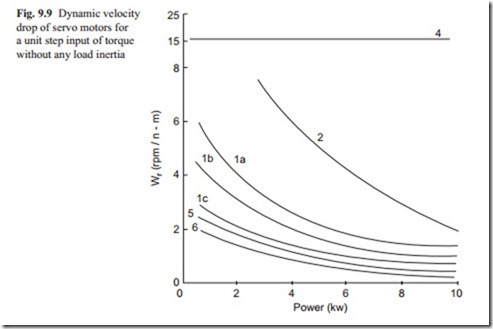
In many applications, the variation in angular velocity due to an external torque is important. Figure 9.9 shows the dynamic velocity drop for a unit step input of torque and without any load inertia. It can be seen that the electrohydraulic motor has the highest velocity drop, followed by AC and DC motors. The speed of recovery is similar to the dynamic settling time, which can be obtained from Fig. 9.6. It appears that the velocity drop for a step input largely depends on rotor inertia. The
dynamic velocity drop usually reduces as the load inertia increases. The rare earth magnet DC motors and the brushless magnet DC motors have the lowest dynamic velocity drop. This is because they can generate a high value of torque for a short period of time.
The type of power unit for DC motors have also influence on Dynamic velocity drop. It can be seen that PWM DC motors have lower dynamic velocity drop com- pared with thyristor controlled DC motors. It can be seen that the dynamic velocity drops for electrical motors reduces as the power rating increases. This is because the larger motors have higher inertia and larger torque capability.
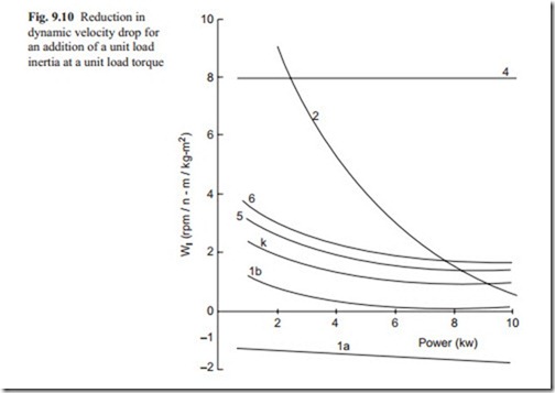
The dynamic velocity drop usually reduces as load inertia is increased. The re- duction in dynamic velocity drop for a unit load inertia and unit torque is shown in Fig. 9.10.
It can be seen that the load inertia reduces the dynamic velocity drop of hydraulic motor considerably, and to a lesser degree for AC and DC motors. The effect of load inertia on stepping motors is negligible, since the error is limited to a maximum of one step, and they are not shown in these graphs. The total dynamic velocity drop, therefore, can be obtained as
where ∇ ωc, ωr, ωl, Te, Il are the total dynamic velocity drop (rpm), dynamic veloc- ity drop for a unit external torque with no load inertia obtained from Fig. 9.9 rpm/ (N M), the reduction in dynamic velocity drop for a unit load inertia and a unit
external torque obtained from Fig. 9.10 (rpm/(kg m2)/NM, the total external torque (NM) and the total load inertia.
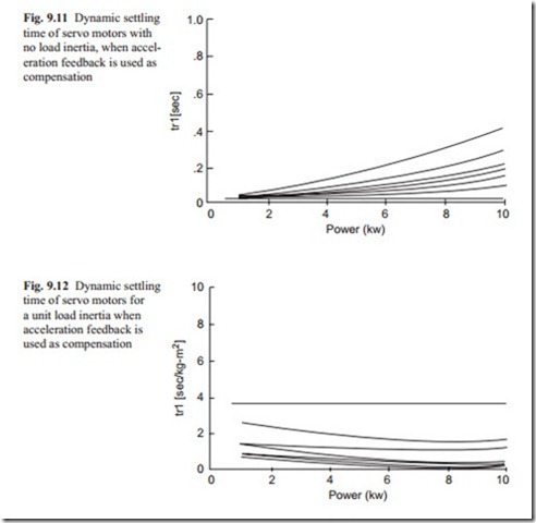
The total speed of recovery is similar to the total dynamic settling time which can be obtained from Figs. 9.6 and 9.7. In this comparison it is assumed that there is a feed-forward integrator to achieve zero steady state error. It was stated earlier that acceleration feedback (which is proportional to the motor current) if available in addition to the velocity feedback improves the dynamic performance further. Figures 9.11 and 9.12 show the dynamic settling time due to rotor and load inertia respectively.
By comparing these graphs with Figs. 9.6 and 9.7, it can be seen that consider- able improvement may be achieved for hydraulic and AC motors. A similar trend of improvement can also be achieved on the effect of external torque.
From the above analysis the design procedure can be summarized as
1. Calculate the equivalent load inertia applied to the motor. If the inertia is variable consider the worst condition, that is, maximum inertia.
2. Calculate the required duty cycle and find the maximum velocity variation and its time duration.
3. Find an approximate power rating from equation, P:=Tω where P is the power, T is the external torque at the angular velocity ω. It should be noted that in addition to external torque some torque must be added to accelerate the total inertia to the required velocity.
4. From eq. (9.1) and Figs. 9.5, 9.6, 9.7, and 9.8 find the total settling time for maximum velocity variation. Compare this settling time with the required time duration of step 2. From the comparison it should be possible to see which types of motors provide the required performance.
5. From Figs. 9.9 and 9.10 calculate the velocity drop due to the applied torque and compare with the permissible value.
6. If from the above analysis none of the motors provide a satisfactory performance, increase the power rating of the motor, and repeat the analysis from step 4.
7. If the higher power rating motor does not produce a satisfactory result then one must use acceleration feedback (or current feedback). Use Figs. 9.11 and 9.12 instead of Figs. 9.6 and 9.7 and repeat the search from step 4.
From the above analysis, one might find that a number of types of servo motors provide the required performance. In this case, the final decision might be based on other criteria such as capital cost, reliability and availability.
To compare capital costs, the complete drive unit must be considered, including the capability of the controller, the number of axes to be driven, the compatibility of possible interface with micro-computer, the addition of velocity and position transducers, and so on. There are indications that for low power rating the hydraulic servo motor drive units are the most expensive. Pulse width modulated systems are the second most expensive and they are followed by thyristor controlled DC motors and AC and stepping motors. At higher power rating, that is, above 10 kW power rating, hydraulic motors become cheaper than electrical motors.
The AC and stepping motors are likely to be the most reliable because both are brushless. Hydraulic motors are reliable but require more maintenance care. The development of brushless DC motors show considerable promise for the future.
Stepping motors are not readily available in large sizes. Hydraulic motors are not available in a wide range of sizes. AC and DC motors are available in almost all power ranges. The availability of rare earth magnet and brushless DC motors is as yet limited to small ranges of power.
