FIBRE OPTICS
During the last hundred years a series of inventions have enabled telecomunication links to be built with ever-increasing capacity. The early telegraph links carried signals at speeds up to about 30 words per minute, or about 15 bits per second. Some of the fibre-optic cable being installed today in the long- distance trunk networks has the capacity to carry signals at a speed of 2.4 Gbps. The theoretical capacity of these hair-thin glass fibres is tremendous. Much fibre optic cable is being installed today, mainly in the long distance and inter-office networks. Over the next ten years, fibre optical cable will be progressively installed as local loops in some areas. In the meantime, however, a multitude of different transmisssion media will continue to be used. It will take some time before all coaxial cable and copper wire systems have been replaced with fibre.
THE TELEPHONE NETWORK
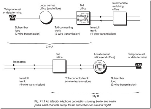
The telephone network is the world’s most complicated machine. When a telephone call is made it may travel over many different types of channels, and complex switching facilities are needed to set up its path. Telecommunications systems can be divided into four main parts.
1. Instruments : The term instrument is used for the device the subscriber employs to originate and receive signals. The vast majority of instruments are telephone hand sets. Today, however, an endless array of other devices are being attached to telephone lines including computer terminals used for data transmission.
2. Local loops : These are the cables that enter the subscriber’s premises. On a telephone network they connect the telephone handsets or other devices to the local switching office (central office). Telephone loops today consist of wire pair cables. Every subscriber has his own pair of wires to the local switching office, and nobody else uses it unless he is on a party line. There are several hundred million miles of telephone subscriber loops. Coaxial cables are also laid into homes by cable television organisations, and these have many potential uses other than television. In the future, high capacity fibre optic cables will be used extensively in the local loop.
If a local call is made, employing only local loops, to the telephone exchange, a larger bandwidth could be obtained, and a faster data rate could be transmitted. Some lengthy local loops have loading coils connected to them. These reduce attenuation but lower the potential bandwidth and bit rate that could be used. To achieve high-speed transmission over the local loops, the loading coils must be removed. Frequencies up to a megahertz can be transmitted over a telephone loop. To transmit such high-frequencies, the signal levels must be carefully coordinated to avoid interference with other services that may be using the higher frequencies on other pairs in the same cable. Generally the gain has to be equalised at short intervals. A baseband data transmission rate of 250,000 bps is generally attainable over unloaded local loops. As the local loop is progressively digitized loading coils become redundant.
The twisted-pair local loop is the weakest link and most costly portion of the telecommunications network. The term weakest link refers to the inability of the local loop to handle high-frequency signals.
The twisted-pair local loop has a narrow bandwidth. The other portions of the PSTN are composed of wide-bandwidth facilities. Voice and data travel across the PSTN on ribbons of fibre which can handle many high-bandwidth signals only to arrive at the local loop which restricts communication to low-frequency analog signals. The local loop is usually from a few hundred feet to several miles in length but it is often referred to as the last mile.
It is technically cost prohibitive to replace the existing wire cables with fibre optic cable and compatible phones in the local loop. To use fibre optic in the local loop, an interface device will be required at every phone to convert electrical energy into light waves. The device could be incorporated in the phone but this would require customers to buy new phones. Twisted-pair copper wire has provided us with a low cost medium to connect telephones to a central exchange and the twisted pair local loop has served as an excellent transmission medium for analog voice signals.
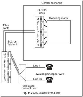
Increasing demand for the ability to place high-speed data signals over the local loop will eventually lead to the deployment of fibre optic facilities to replace all, or a portion of the local loop. The first phase of fibre introduction into the local loop has to use fibre as a main feeder cable to serve a segment of exchange territory. Multiple subscriber line carrier systems (SLC-96s in Fig 41.2) are placed on a multiplexer in the central office. Each SLC-96 connects to 96 line circuits. Demultiplexers are placed at several locations along the fibre route, and several SLC-96 field units are placed on the demultiplexer.
3.Switching facilities : An elaborate network of switching offices enables any telephone to be connected to almost every other telephone. Most of the switching and control functions are carried out entirely by computers. Some electromechanical facilities will continue to exist in less populated areas for a few years.
4. Trunk Circuits : Trunk circuits are transmission links which interconnect the switching offices.
Such links normally carry more than one telephone call. On high-traffic routes, they carry many thousands of calls simultaneously. A variety of different transmission media is employed including wire pairs, coaxial cables, microwave radio, satellites, and fibre optics.
NONVOICE TRAFFIC
For half a century telephone technology has dominated telecommunications. There have been 1000 times as many telephone subscribers as other types of telecommunication users. Consequent economics of scale have dictated that telegraph and data traffic should be converted to a form in which they can travel over the telephone system.
Since 1970s new types of common carriers emerged and built their own non telephone networks. Separate data transmission networks for computer users are available in all major industrial countries. Some of these operate by attaching special equipment to the telephone networks. Others employ new transmission networks, physically separate from the telephone networks.
Telephone traffic and computer traffic have characteristics so different that different network architectures are needed.
TELEPHONE USERS
(i) Require a fixed capacity channel.
(ii) Always carry out a a two-way conversation.
(iii) Tolerant of noise on the channel.
(iv) Transmit or listen continuously until the call is disconnected.
(v) Require immediate delivery of the signal.
(vi) The transmission rate is constant.
(vii) The time to set up the connection can range from a few seconds to 1 minute (maximum).
COMPUTERS AND THEIR TERMINALS
(i) Require a very wide spread of channel capacities ranging from a few bits per second to millions of bits per second.
(ii) One-way or two-way transmission.
(iii) Data must be delivered without errors.
(iv) In a man-computer dialog, transmission is in bursts.
(v) In non-real-time data transmission the data can be delivered later, when convenient.
(vi) In a man-computer dialog the mean number of bits per second is usually low, but the peak requirement is often high. The peak-to-average ratio is often as high as 1000.
(vii) It is desirable that the connection be set up in a second or less.
Computer users have fundamentally different characteristics and requirements to plain old telephone service. Table 41.1 summarises the differences. An important difference is the peak-to-average transmission requirement. It is 1 in telephone conversations but can be 1000 or even higher in human-computer dialogs. The higher the peak/average ratio, the greater the inefficiency of using a transmission channel which transmits at a constant fixed rate. Instead a channel is needed which transmits bursts of data when they are required with a suitable short response time. Such a channel can be derived either by using suitable equipment to share a fixed-rate channel or by using a common carrier network architecture which allocates capacity on a rapidly time-varying basis.
FIBRE IN LOCAL LOOP
Basically, there are four ways to reach the local telephone company’s end office, that is, there are only four ways to implement the local loop): copper wire, coaxial cable, fibre optic cable, and wireless communication. The copper is owned by the local phone company and they try to cram as much information as is technologically possible. The coaxial cable is owned by the local cable company. They too are trying to cram as much information down the cable as is technologically possible. Today, running fibre optic cable to individual homes is considered infeasible. And then there is wireless.
To date the majority of optical-fibre- systems have been installed in the trunk and inter-office network. The next stage is the introduction of fibre optics into the local loop, taking a fibre cable right into a subscriber’s office or home. For many new local subscriber networks, it would be cheaper to instal fibre cable than copper. By using wave-division multiplexing techniques both the incoming and outgoing signals can be multiplexed onto a single fibre; so only one fibre is needed per household. The potential of having fibre in local loop is enormous. The 565 Mbps systems currently operating in the trunk network can easily be applied to the local loop. A single 565 Mbps cable into the home could, for example, provide the following:
● Eleven simultaneous 50 Mbps high-definition television (HDTV) channels with compression
● Eleven 50 Mbps data channels
● Numerous channels for; videophones; music; ordinary voice channels; telemetry; photographic- quality colour facsimile television and video wall screens; access to vast music and video libraries.
The nature of the telephone network is such that improvements in bandwidth tend to be implemented first in the trunk network, and they gradually cascade down to the subscriber as the cost of new technology reaches a point where implementing into offices and, later, homes of millions of subscribers becomes economical.
In future, optical technology in the form of transmission and switching will dominate telecommunications. The impact this will have on how and what we communicate is likely to be as revolutionary as was the invention of the telephone itself.
OPTICAL SYSTEMS
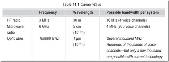
Although many lasers and LEDs are able to produce outputs in the visible light band, most current optic fibre telecommunication systems (Fig. 41.3) use signals of wavelengths 0.8 µm to 1.3 µm, both in the infrared band. These are still called optical systems: even though the signals cannot be seen they are transmitted in exactly the same way as visible light signals. The main reason why engineers wanted to be able to modulate coherent light was to take advantage of the tremendous bandwidths which could be carried by these very high-frequencies. The figures below are typical figures, indicating the orders of magnitude involved.
OPTICAL FIBRE CABLE
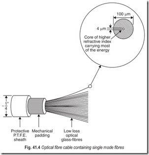
An optical fibre cable consists of a glass core that is completely surrounded by glass cladding (Fig. 41.4). The core performs the function of transmitting the light waves, while the purpose of the cladding is to minimise surface losses and to guide the light waves. The glass used for both the core and the cladding must be of very high purity since any impurities present will cause some scattering of light to occur. Two types of glass are commonly employed : silica-based glass (silica with some added oxide) andmulti component glass (e.g. sodium borosilicate).
Some new optic fibres do not use glass at all, but special types of plastic; these are usually cheaper to make than very pure glass but introduce greater attenuation. Fibres now being manufactured are so free from impurities that very little energy is lost as the signals travel along. An attenuation of less than 1 dB per kilometre is not uncommon for the latest high-purity silicons.
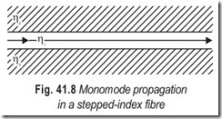
A major constraint with optic fibres (apart from the straight forward one of attenuation) is that since the wavelength of light is very short a light wave signal injected into one end of an optic fibre (sometimes called an optic wave-guide) does not merely travel straight down the middle of the core. It swings from side to side, continually being reflected or refracted back from the core/cladding surface. Clearly a pulse going straight down the middle will reach the end just before those parts of the same pulse signal which have zigzagged along, taking a longer path. This places a restriction on the maximum possible bit rate that may be transmitted satisfactorily in the fibre.
TYPES OF OPTICAL FIBRE
It would have been ideal if right from the beginning we could have used fibres made with tiny diameters comparable with the wavelength of the optical signal being used, so that no zigzagging was able to take place, but the manufacture and joining of such high-precision fibres presents considerable difficulty. Today’s more common thicker-core fibres are called multimode (because many different modes of transmission are possible). Fibres with very small diameter cores are called monomode (because only a single mode of transmission is possible). There are three basic types of optial fibre:
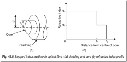
1. Stepped-index multimode: The basic construction of a stepped-index multimode optical fibre is shown in Fig. 41.5 (a) and its refractive index profile is shown in Fig. 41.5 (b). It can be seen that an abrupt change in refractive index of the fibre occurs at the core/cladding boundary. The core diameter, 2r1 , is usually 50–60 µm but in some cases may be up to about 200 µm. The diameter 2r2 , of the cladding is standardised whenever possible at 125 µm.
Stepped-index multimode fibre produces large transit time dispersion (Fig. 41.6) so its use is restricted to applications such as those involving comparatively low speed data signals.
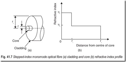
2. Stepped-index monomode: Figure 41.7 (a) shows the basic construction of a stepped index monomode optical fibre and Fig. 41.7 (b) shows its refractive index profile. Once again the change in the refractive indices of the core and cladding is an abrupt one but now the dimensions of the core are much smaller. The diameter of the core is of the same order of magnitude as the wavelength of the light to be propagated, it is therefore in the range 1–10 µm. The cladding diameter is the standardised figure of 125 µm.
Stepped-index monomode fibres are at present difficult and expensive to manufacture and join, so most of the stepped-index optic-fibre telecommunication systems now installed use multimode fibres. As the technological difficulties are overcome the use of monomode fibres may well increase.
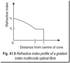
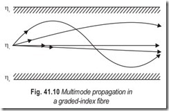
3. Graded-index multimode: The basic construction of a graded index multimode optical fibre is the same as that of a stepped index multimode fibre shown in Fig. 41.5 (a). The core diameter is also in the range 50–60 µm and the cladding diameter is 125 µm. The refractive index of the inner region or core is the highest at the centre and then decreases parabqlically towards the edges, Fig. 41.9, to that of the cladding material. This means that light waves will be refracted back from the outer boundary of the fibre, and not reflected as with stepped-index fibres (see Fig. 41.10). So waves will go straight down the centre of the core or zig-zag from side to side as they do in stepped- index fibre, but in a smoother manner. The main difference is, however, that waves which zig-zag along in a graded index fibre pass through regions with a lower refractive index than in the central part of the core, so although they travel a greater distance, it is at a higher velocity. The effect of this is to reduce the differences in the times taken by the many different modes; ideally, all modes then arrive at the distant end in exact synchronism.
No matter which of the three possible types of propagation is used, the dimensions of the outer medium or cladding must be at least several wavelengths. Otherwise some light energy will be able to escape from the system and extra losses will be caused by any light scattering and/or absorbing objects in the vicinity.
OPTICAL FIBRE ADVANTAGES AND DISADVANTAGES
Fibre optic cabling is immune to electrical interference. Signals are transmitted in the form of ‘off and on’ light pulses similar to a flash light. No electricity is present in transmission over fibre. Thus signals carried on strands of fibre do not interfere with each other. Therefore fibre can be run in areas without regard to interference from electrical equipment.
Advantages of fibre cabling are:
1. Low transmission loss: This permits longer repeater sections than with coaxial cable systems, thereby reducing costs.
2. Wide bandwidth: This means a large channel carrying capacity.
3. Small cable size and weight: This means that drums of cable can be run economically and that each cable uses less space in cable ducts.
4. Immunity to electromagnetic interference: This permits use in noisy electrical environments, such as alongside electrified railway tracks and means that low signal-to-noise ratios are acceptable.
5. Non inductive: The fibre does not radiate energy so causes no interference to other circuits.
Communication security is thereby enhanced.
6. Long-term cost advantages: The basic raw material silica is never likely to be in short supply and improved technology is continually producing lower cost and more efficient devices.
Disadvantages of fibre cabling are:
1. Termination, component and connector costs: These are higher than for copper wiring. Special equipment is required to terminate fibre cables within buildings, test and splice fibre and to convert electrical signals to light pulses and vice versa.
2. More care in handling: Fibre is not as flexible as twisted pair in bending around coners, therefore, more care in handling fibre is needed.
Local electrical power is required: When fibre is brought into buildings from telephone companies
or to curb in residential areas local electrical power is required. This adds a point of vulnerability in the event of a power outage.
1. Specialised technicians: Who might be paid at higher levels, often are required to work with and test fibre cabling.
EXERCISES
Descriptive Questions
1. Telecommunication systems can be divided into four main parts. Explain
2. Compare telephone traffic with computer traffic.
3. Illustrate and explain the basic principles of fibre-optic communication.
4. What are the types of optic fibre?
5. What are the advantages and disadvantages of optical fibre?
6. Write short notes on the following:
(a) Fibre in local loop (b) SLC-96
(c) Optical fibre cable
Fill in the Blanks
1. The term instrument is used for the device the subscriber employs to ………………………… signals.
2. Local loops are the cables that enter the………………………… premises.
3. Loading coils reduce………………………… but lower the potential bandwidth and bit rate that could be used.
4. To achieve high speed transmission over local loops, the loading coils must be………………………… .
5. Generally the gain has to be equalised at………………………… .
6. The twisted pair local loop is the………………………… link.
7. The twisted pair local loop has a………………………… bandwidth.
8. Most of the switching and control functions are carried out entirely by………………………… .
9. Trunk circuits are………………………… which interconnect the switching offices.
10. Telegraph and data traffic should be………………………… to a form in which they can travel over the telephone system.
11. There are only………………………… ways to implement a local loop.
12. Improvements in bandwidth in a telephone network tend to be implemented first in the………………………… and then gradually cascade down to the subscriber.
ANSWERS
Fill in the Blanks
|
1. originate and receive |
2. subscriber’s |
3. attenuation |
|
4. removed |
5. short intervals |
6. weakest |
|
7. narrow |
8. computers |
9. transmission links |
|
10. converted |
11. four |
12. trunk network |
