DATA SERVICES
For most of its past history, telecommunications has been dominated by analog switching, transmission and frequency–division multiplexing. Telecommunication, networks in the 1980s underwent a process of rapid change. The conventional analog telephone was replaced steadily by computer controlled digital networks of immense capacity. The conversion of all telecommunication networks to digital switching and transmission will take some considerable time. Until then, digital and analog facilities must coexist, particularly in many developing countries. Voice is no longer the dominant feature around which networks are designed. From now on networks should carry all types of signals in a digital fashion.
The key concept of a digital network is that it lays the foundation for creating an ubiquitous integrated network capable of handling all our communications requirements, from a simple telephone call to the broadcasting of high definition television.
WHY DIGITAL?
What are the advantages of transmitting the telephone voice in digital form? One of the major advantages existed on early teletype links, but when several teletype channels were multiplexed into one voice circuit, the advantage was lost. Now the changing economies are bringing it back. With analog transmission, whenever the signal is amplified, the noise is amplified alongwith it. As the signal passes through its many amplifying stations, the noise is cumulative. With digital transmission, however, each repeater station regenerates the pulses. New, clean pulses are reconstructed and sent on to the next repeater, where yet another cleaning-up process takes place. So the pulse train can travel through a dispersive noisy medium but, instead of becoming more and more distorted until eventually parts are unrecognizable, it is repeatedly reconstructed, thus remaining impervious to most of the corrosion of the medium. Of course, an exceptionally large noise impulse may destroy one or more pulses so that they cannot be reconstructed by the repeaters.
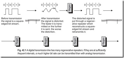
A major disadvantage of digital transmission would appear to be thatmuch greater bandwidth is required. However, since the signal is reconstructed at frequent intervals down the line, it can tolerate much more battering than if it had to travel a long distance without reconstruction. It can survive traveling over a channel with a high level of distortion and with a poor signal-to-noise ratio. The trick that makes digital transmission worthwhile is to reconstruct the signal repeatedly so that it survives the bad distortion. A high bit rate can then be transmitted. This is shown in Fig. 42.1.
Consider a telephone wire pair under the streets of a city. With analog transmission it can carry a channel group-12 voice channels. Now suppose that we transmit digitally over the same wire pair. The digital signal becomes distorted as it is transmitted, as shown in Fig. 42.1. We catch it before it becomes too distorted to recognize whether a bit is 0 or 1. The bit stream is then reconstructed, retimed and retransmitted. The faster a bit stream is transmitted, the greater will be the distortion and the closer the spacing of repeaters necessary to reconstruct the signal correctly. How closer can they reasonably be spaced? There is a manhole or other access to the wires about every 600 feet. With that spacing, today’s telephone wire pairs can be made to carry 2.048 Mbps, which is equivalent to 32 telephone speech channels.
DIGITAL EXCHANGES
It has been conventional to divide telephone exchanges into two main categories : space division (or analog), and time division (or digital).
1. Space Division (or Analog) – in which direct physical paths are established right through the exchange from one subscriber’s line to another. Connections may be metallic contacts or by solid-state analog devices.
2. Time Division (or Digital) – in which some or all of the switching stages in the exchange operate by shifting signals in time. Basically a connection is made between incoming and outgoing channels by transferring each PCM word from the time-slot of the incoming channel to that of the outgoing channel. This time-shifting is carried out by means of stores. Information is written into an address in a store, then during every cyclic scan the information from that particular address is read out so that it occupies the required outgoing time-slot.
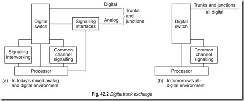
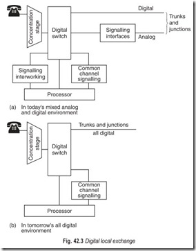
Most digital exchanges are built from subsystems. These subsystems can be put together to provide a variety of exchanges for use at different points in the network (see Figs. 42.2 and 42.3). The simplification of function which follows the final elimination of FDM and analog trunks and junctions will be apparent. When this stage is reached, exchanges will take up a fraction of the floor area now occupied with great consequent savings.
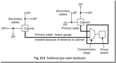
The function of the concentration stage is to interconnect subscriber lines with the main switching subsystem in the exchange, the digital or group switching stage. The concentration stage has to be carefully designed to provide the grade of service required by the administration, with the greatest possible economy. Business lines are used much more than residential lines, so it is not possible to concentrate business lines to the same extent as low calling rate residential lines. Junctions to other exchanges are not concentrated at all; every trunk and junction circuit always has direct access to the group switch.
When a concentration stage serves the called subscriber, it is sometimes called the expansion stage, and shown separately even though it is sometimes the same piece of equipment as the concentration stage.
THE BORSCHT FUNCTIONS
The interface with the subscriber’s line is at present the costliest part of all digital exchanges, largely because a 10000 lines exchange has to have 10000 of these units, each with all the features needed to inter work with various types of subscribers’ lines. It is customary to describe these features as the BORSCHT functions, based on the initials of the key words.
1. Battery feed to line – there is normally no active power source at the subscribers’ telephone; all the power, needed to drive the microphone and keypad, is fed out from the exchange along the subscriber’s line.
2. Overvoltage protection – solid-state devices are very sensitive to high voltages, and rapid-action protective devices have to be provided in each line circuit so that if lightning does happen to strike an external line the exchange will not be put out of action.
3. Ringing current injection and ring trip detection – the bell at the called subscriber’s telephone has to be rung; this means that quite a high voltage. an ac signal (sometimes about 70 volts) has to be connected to the line, to ring the bell; and as soon as the handset has been picked up off its cradle (gone off hook) the ringing must be tripped and disconnected.
4. Supervision of the line – equipment has to be provided which continually monitors the line so that as soon as it goes off hook (and a continuous dc path provided through the instrument) the exchange connection is activated and dial tone sent out to the caller. Dial pulses represent breaks in the continuous dc loop; these have to be detected and counted so that the exchange knows what number is required. When the caller finally clears down, by going back on hook the exchange must break down the established call and note the time at which this has been done for charging purposes.
5. Codec (short for encoder plus decoder) – this turns the analog signal received from the telephone instrument into a digital signal ready to be multiplexed with others, into a PCM signal. Incoming signals are similarly decoded from digital to analog before being sent out to the subscriber’s instrument. Some digital exchanges have one codec per line; some share codecs between several lines; some use even fewer codecs by placing them between their concentration stages and the links going to their group switching stages.
6. Hybrid for 2-wire to 4-wire conversion – the line to an ordinary telephone subscriber uses one pair of wires, for both directions of conversation; this is called a 2-wire circuit. The circuits inside a digital exchange use two electrically separate paths, one for each direction of transmission; this is called a 4-wire circuit. To join together a 2-wire and a 4-wire circuit, a special device called a hybrid coil is used; this allows speech from the 2-wire line to enter the 4-wire transmit path, and speech from the 4-wire receive path to 2-wire line, but it blocks speech incoming on the 4-wire receive path from going out again on the 4-wire transmit path of the same circuit. Ordinary electro- mechanical exchanges use 2-wire circuits all the way through so there is no need for hybrids in these exchanges.
7. Testing of both line and equipment – it is necessary to be able to test the subscriber’s line electrically so that faults may be located and cleared.
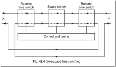
Any form of time-division switching is a one-way function, to provide a single bi-directional speech circuit through an exchange, two-channels, therefore, have to be switched through, one for each direction of transmission. Figure 42.4 shows how this is done in some exchanges.
LOCAL DISTRIBUTION NETWORKS
The connection between the subscriber and local telephone exchange consists of a pair of wires in a telephone cable. Since a large telephone exchange may have 10000 or more subscribers, the local line network can be quite complicated, particularly because provision must be made for fluctuating demand. The local line network is provided on the basis of forecasts made of the future demand for telephone service, the object being to provide service on demand and as economically as possible.
Since the demand fluctuates considerably there is the problem of forecasting requirements and deciding how much plant should be provided initially and how much at future dates. No matter how carefully the forecasting is carried out, some errors always occur and allowance for this must be made in the planning and provision of cable, i.e. the local network must be flexible. A network must be laid out so that the situation should not arise where potential subscribers cannot be given service in some parts of the exchange area while in other parts spare cable pairs remain.
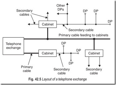
The modern way of laying out a local line network is shown in Fig. 42.5. Each subscriber’s telephone is connected to a distribution point, such as a terminal block on a pole or a wall. The distribution points are connected by small distribution or secondary cables to cabinets. Primary cables then connect these cabinets to the telephone exchange.
It is usual to provide secondary cables on the basis of an expected life of about 15 years and the much larger primary cables for only about 5 years. This does not mean that these cables are expected to be scrapped after these periods; they are expected by then to be fully utilised and to require supplementing by additional cables. Cabinets are sometimes called flexibility points: if demand is much heavier than forecast in one part of the area served by the cabinet, and less in another part, cable pairs may be connected through at the cabinet to the faster developing area.
It is usually economically desirable to use underground ducted cable from exchange to flexibility points (cabinets) and then either go underground or overhead to distribution points depending on circumstances. A ducted system, although initially more costly than a direct buried system provides much greater flexibility for the future installation of additional cables, and facilitates cable repairs or replacement.
At the present time, polyethylene-insulated, conductors and polyethylene-sheathed cable incorporating an aluminium screen and water vapour barrier is the most economical type of cable to be used in ducts. Main or primary cables from exchanges to cabinets should wherever possible be dispersed with protection provided by continuous flow dry air pressurisation. Secondary or distribution cables from cabinets to distribution points (and smaller main cables) should be jelly-filled, not pressurised. Aerial cables should be of similar design but with an in-built self-supporting catenary wire in the figure-of-eight mode.
Many modern telephone switching systems incorporate concentration stages which can be either co- located (i.e. in the same building as the rest of the exchange) or remote (i.e. many kilometres away, fed by PCM systems back to the main part of the exchange). Remote concentrators need accommodation and power supplies, and have to be maintained. As time goes on it seems probable however that digital concentrators will become more and more compact and will soon usually be accommodated in roadside cabinets like the cable cross-connection cabinets now is general use. Or perhaps concentrators may soon be designed round so few integrated circuits that they will be put into sealed canisters which can be joined in to the cable network and installed inside ordinary underground joining chambers and manholes.
DATA SERVICES
Communication of discrete messages (data) is actually an ancient practice. In ancient times communication over distances greater than the range of human voice was provided by sight or sound of discrete signals. Further more, the first practical communication system to use electricity, the telegraph, is inherently digital. As telegraphy evolved from the original, manually based systems to fully automated systems, they developed into what are commonly referred to as message-switching networks.
As the need for modern electronic data communications increased, it was only natural that the telephone network would be used for data transmission services. The availability overshadowed numerous technical shortcomings of a network designed primarily for voice communication services. The main drawbacks of a conventional telephone network for data transmission are :
1. Need for signal transducers (modems) on analog access lines
2. Limited data rates
3. High error rates (in the older analog network)
4. Inefficient circuit utilisations
As data communications requirements increased, so did the justification for more cost-effective data communication solutions. The first approach to reducing data transmission costs was to improve circuit utilisation through the use of packet-switching networks. The technology for packet switching was pioneered by the Advanced Research Projects Agency of the US government. This agency developed a network referred to as the ARPANET, which eventually evolved into what is now known as the INTERNET.
A second approach to improving data communications involves developing separate networks specifically designed for digital transmission (no analog circuits with modems). Because the data communications market place of the time could not support a separate, dedicated network for data, it ran into financial difficulty.
The third approach was the Dataphone Digital Service (DDS) offered by AT&T. This service utilises digital technology of the telephone network for strictly data application. DDS circuits are dedicated to data services, but the facilities and routes are shared with telephone network facilities. A major hurdle for DDS is achieving digital access to DDS circuits. If a subscriber is outside the range of digital transmission facilities of a DDS serving office, a voiceband modem over an analog line is required.
The fourth approach to satisfying data communications services involved developing means for directly accessing the digital transmission and switching equipment of the telephone network. The first widespread approach of the telephone companies for providing universal digital access is the Integrated Services Digital Network. ISDN provides digital access to digital facilities of the telephone network for voice or data services on a call-by-call basis.
MESSAGE SWITCHING
As one telegraph system after another was installed in the countries around the world, nationwise communications networks evolved. A message could be sent from one point to another even if the two points were not serviced by a common telegraph line. In this case, telegraph operators at intermediate points would receive a message on one line and retransmit it on another when a telegraph office had several lines emanating from it, the process of transferring a message from one line to another was, in essence, a switching function.
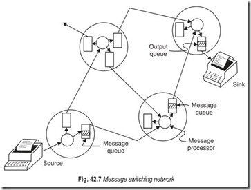
One of the world’s largest message switches was completely automated in 1963 when Collins Radio Company installed a computer-based message switch for airline companies of North America. This system and the more recent successors store incoming messages directly into a computer memory (disk file) and forward them automatically to the appropriate output line when available. Hence this mode of operation is often referred to as store-and-forward message switching.
Included with each message is a header containing an address and possibly routing information so the message processor at each node can determine to which output line to switch the message. The processor in each node maintains message queues for each outgoing link, Fig. 42.7. These queues are normally serviced on a first come, first served basis. However, priority information can sometimes be included in each header to establish different classes, or grades of service, thereby allowing time-critical messages to be placed at the head of a queue.
MESSAGE SWITCHING AND CIRCUIT SWITCHING
A message switching network is fundamentally different from a circuit switching network in that the source and destination do not react in real time. In fact, most message switching networks could deliver a message on a delayed basis if a destination node is busy or otherwise unable to accept traffic. In a message switching network there is no need to determine the status of the destination node before sending a message, as there is in circuit switching.
Message switching networks are fundamentally different from circuit switching networks in their response to traffic overloads. A circuit switching network blocks or rejects excess traffic while a message switching network normally accepts all traffic but provides longer delivery times as a result of increased queue lengths.
Yet another important distinction of a message switching network is that the transmission links are never idle while traffic is waiting to use them. In a circuit switching network, a circuit may be assigned to a
particular connection but not actually carrying traffic. Thus, some of the transmission capacity may be idle while some users are denied service. In contrast utilisation of the transmission links of a messages witching network is directly related to the actual flow of information. Arbitrarily high utilisation efficiencies are possible if increased store-and-forward queuing delays are acceptable.
PACKET SWITCHING
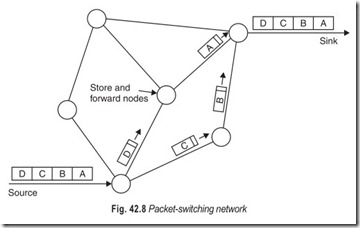
Figure 42.8 depicts both the conceptual structure and the conceptual operation of a packet switched network. A single message at the source is broken up into packets for transmission through the network. Included in each packet is a header containing address and other control information. Each packet is relayed through the network in a store-and-forward fashion similar to a message switching network. At the destination node, the packets are reassembled into the original contiguous message and delivered.
The main feature of a packet switching operation is the manner, in which the transmission links are shared on and as-needed basis. Each packet is transmitted as soon as the appropriate link is available, but no transmission facilities are held by a source when it has nothing to send. In this manner, a large number of relatively inactive sources can share the transmission links. In essence, link utilisation is improved at the expense of storage and control complexity in the nodes. Considering the declining cost of digital memory and processing, the increased control complexity becomes less and less significant as digital technology advances.
One particular variation of packet switching Asynchronous Transfer Mode (ATM) is designed to specifically support hardware implementations of control intensive functions, thereby supporting very high traffic volumes with low delay.
As the traffic load in a packet switched network increases, the average transmission delay increases correspondingly. In contrast, a circuit switched network either grants service or rejects it. Conversely when only a few circuits are in use in a circuit switched network, much network transmission capacity is idle. When there is a light load on a packet switched network, the active users benefit by shorter than usual delay times.
Using automatic repeat request (ARQ) error control, packet switching networks traditionally provided essentially error-free transmission for each node-to-node transfer. When errors are detected a retransmission is requested (message NAK). Hence transmitting nodes must hold all transmitted packets in memory until a positive response (message ACK) is returned by the receiving terminal. Further more, an entire packet is usually received and checked for errors before forwarding it to another node.
Customers typically access packet networks by way of leased lines or dial-up connections. Dial-up connections are used by infrequent users, while leased lines are preferred by heavy users to achieve constant availability, higher data rates, and possibly low error rates.
PACKET SWITCHING AND MESSAGE SWITCHING
Despite the similarity to message switching operations, a packet switching network is different in two important respects :
1. The store-and-forward delay through a packet switched network is relatively short. Thus interactive communications can occur in much the same manner as if a dedicated end-to-end circuit is established.
2. A packet switched network does not provide storage of messages, except in an incidental manner while relaying packets from one node to another. The network is designed to provide switched communication between two nodes, both of which are actively involved in the communication process. A packet switching network does not normally store a message for later delivery to an inactive or busy terminal.
PACKET FORMAT
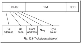
As indicated in Fig. 42.9, a packet contains three major fields : the header, the message, and the redundancy check bits. Generally speaking, the control information associated with a particular message or link is included in the header of a message packet. Some packets may not contain a message field if they are being used strictly for control purposes. Although a variety of techniques for generating redundancy checks are possible, the most popular technique uses cyclic redundancy checks (CRCs). Basically, a CRC is nothing more than a set of parity bits that cover overlapping fields of message bits. The fields overlap in such a way that small number of errors are always detected and the probability of not detecting the occurrence of 2 large number of errors is 1 in 2M, where M is the number of bits in the check code.
A header typically contains numerous subfields in addition to the necessary address field. Additional fields sometimes included are :
1. An operation code to designate whether the packet is a message (text) packet or a control packet. In a sense this field is a part of the destination address with the address specifying the control element of a switching node.
2. A source address for recovery purposes or identification of packets at a destination node that is capable of simultaneously accepting more than one message.
3. A sequence number to reassemble messages at the destination code, detect faults, and facilitate recovery procedures.
4. A length code to indicate the length of a packet when less than a standard size pack is transmitted.
LAN, MAN, AND WAN
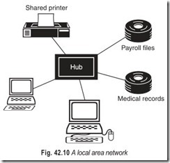
Computers in homes and offices are connected together by local area networks (LANs), located within a building or in a campus environment. LANs link computers, printers, scanners and shared devices such as modems, video conferencing units and facsimile machines to each other and to the internet (Fig. 42.10). A discrete LAN is typically located on the same floor or within the same department of an organisation.
Each device connected to the LAN can communicate with every other device. The connections between devices may be any of the following : twisted pair, coaxial cable, fibre optics or wireless media. For the most part, devices are connected to a LAN by twisted pair cabling that is similar to but sometimes of a higher quality than that used to tie business telephones together.
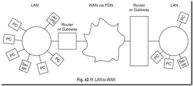
We can connect two LANs together that are close to Fig. 42.10 A local area network one another (such as within the same building) using a device called a bridge. We can connect LANs to each other if they are within a larger geographic region (such as a city) using a metropolitan area network (MAN) and we can connect LANs separated by any distance using a wide area network (WAN). The basic first step to getting all computers set up so that they have access to all other computers is to get a LAN established for each group of computers. MANs and/or WANs can then be used to connect the LANs together.
A MAN occupies a middle ground between LANs and WANs. MANs cover greater distances at higher data rates than LANs, although there is some overlap in geographical coverage.
The primary market for MAN is the customer that has high capacity needs in a metropolitan area. A MAN is intended to provide the required capacity at lower cost and greater efficiency than obtaining an equivalent service from the local telephone company.
WANs cover a large geographic area, may require the crossing of public rights of ways and may rely atleast in parts on circuits provided by a common carrier. Typically, a WAN consists of a number of interconnected switching nodes. A transmission from any one device is routed through these internal nodes to the specified destination device. High-speed WANs provide user connections in the 10s and 100s of Mbps, using a transmission technique known as asynchronous transfer mode (ATM).
INTEGRATED SERVICES DIGITAL NETWORK (ISDN)
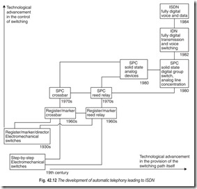
Integrated services digital network is a single network able to carry and switch a wide variety of telecommunication services, voice, video, data or packets over the public switched telephone network (PSTN). It is expected to evolve from an IDN, an integrated digital network, which is a telephony network in which digital transmission systems have been fully integrated with switching systems (Fig. 42.12).
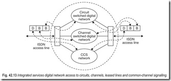
ISDN is a service offering that extends access to digital transport facilities and to the signalling network. Access to the digital transport facilities occurs on 64 kbps (B) channels while access to signalling network occurs on 16 or 64 kbps signalling (D) channels (Fig. 42.13).
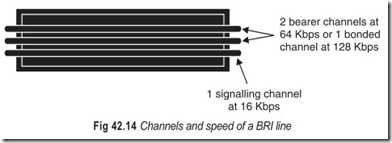
Two levels of digital access to the ISDN network have been standardised : basic rate access and primary rate access. As shown, the worldwide basic rate interface (BRI) standard is also referred to as 2B+D interface. It consists of two bearer channels for customer voice or data at 64 kbps. In addition, it has one 16 kbps signalling channel. It runs over a single pair of twisted wires between the customer and the telephone company.
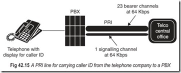
The primary interface (PRI) is sometimes referred to 23B+D interface (Fig 42.15). PRI ISDN is a trunk connection. It is installed on the trunk side of a PBX or into a multiplexer. BRI ISDN is a line-side connection. It connects to the same ports in PBXs as do telephone sets.
Many corporations use PRI ISDN for their direct inward dialing (DID) traffic. The local telephone company sends the caller’s names and phone number over the signalling channel. The telephone system captures the information and sends it to the display equipped ISDN telephone. Fig 42.15 illustrates a PRI line for transporting caller ID. Employees who receive heavy volumes of calls from vendors or who only take calls from certain callers use ISDN to screen calls. Calls not taken are forwarded automatically into voice mail.
THE INTERNET
In most cases a LAN or a WAN is not an isolated entity. An organisation may have more than one type of LAN at a given site to satisfy a spectrum of needs. An organisation may have multiple LANs of the same type at a given site to accommodate performance or security requirements. And an organisation may have LANs at various sites and need them to be interconnected via WANs for central control of distributed information exchange.
An interconnected set of networks from a user’s point of view may appear simply as a larger network. However, if each of the networks retains its identity and special mechanisms are needed for communicating across multiple networks, then the entire configuration is often referred to as the internet. The most important example of an internet is referred to simply as a research-oriented packet switching network. It has served as the basis for the development of internetworking technology and as the model for private internets within organisations. The latter are also referred to as intranets.
Each constituent subnetwork in an internet supports communication among the devices attached to that subnetwork; these devices are referred to as end systems (ESs). In addition, subnetworks are connected by devices referred to as intermediate systems (ISs). ISs provide a communication path and provide the necessary relaying and routing functionsso that data can be exchanged between devices attached to different subnetworks in the internet.
Although the internet has grown tremendously, many households still lack PCs and internet access. Thus the area is still ripe for continued growth. It is just as important to have a PC and internet access as it was to have a telephone or television 50 years ago. Over time, the telephone and TV came to be seen as necessities. Internet access and a PC in every home will follow along the same lines.
The World Wide Web (WWW) organises the resources of the internet, which consist of many computers linked together via high-speed data facilities. These computers contain files that are accessed by internet surfers. The collection of files available on the internet are usually accessed by a web browser.
EXERCISES
Descriptive Questions
1. What are the advantages of transmitting voice in digital form?
2. What is the major disadvantage of digital transmission?
3. In digital transmission, the bit stream is “reconstructed, retained, retransmitted”. Explain.
4. Differentiate between a time-division and a space-division telephone exchange.
5. Explain the function of a concentration stage.
6. Differentiate between a concentration stage and an expansion stage.
7. What do the BORSCHT functions signify?
8. Briefly explain local distribution networks.
9. Differentiate between circuit switching, message switching and packet switching.
10. With the help of a suitable illustration explain a typical packet format.
11. Differentiate between LANs, MANs and WANs.
12. How ISDNs have evolved?
13. Differentiate between a BRI and a PRI. Give the channels and speed for both.
14. What is the significance of internet and worldwide web?
15. Write short notes on:
|
a. Regenerator |
b. Digital trunk exchange |
c. Codec |
|
d. 2-wire circuit |
e. 4-wire circuit |
f. Primary cables |
|
g. Secondary cables |
h. Message switching |
i. Header |
|
j. CRC |
Fill in the Blanks
1. With space division exchanges ……………………. physical paths are provided, through the exchange, from one subscriber line to another.
2. With digital exchanges switching stages operate by……………………. signals in time.
3. Concentration stages provide the required grade of service with the greatest possible……………………. .
4. When a concentration stage serves the called subscriber it is sometimes called an ……………………. stage.
5. BORSCHT functions are based on the initials of the……………………. words.
6. To join together a 4-wire circuit and a 2-wire circuit a……………………. coil is used.
7. Any type of time-division switching is a……………………. function.
8. Local distribution networks provide……………………. and as economically as possible.
9. The local network must be……………………. .
10. The distribution points are connected by……………………. cables.
11. An entire packet is usually received and checked for……………………. before forwarding it to another node.
12. A header contains numerous……………………. in addition to the address field.
13. LANs that are close together are connected by a……………………. .
14. We connect LANs separated by any distance using……………………. .
15. A MAN occupies a middle ground between……………………. and WANs.
16. ISDN is a single network able to……………………. a wide variety of telecommunication services.
ANSWERS
Fill in the Blanks
|
1. direct 4. expansion 7. one-way |
2. shifting 5. key 8. service on demand |
3. economy 6. hybrid 9. flexible |
|
10. secondary 13. bridge 16. carry and switch |
11. errors 14. WANs |
12. subfields 15. LANs |
