DATA CONVERSION
The term data conversion refers to the translation of analog signals into digital form and vice versa. While it used to be an all-analog electronics world, today it is virtually all digital. We still have analog signals such as voice, video, radio waves, and sensor voltages, but mostly we process, store, and transmit data by digital means. For that reason, circuits that perform these conversions are criti- cal to virtually all electronic applications. All cell phone voice is digital, all modern TV is digital, and sensor outputs are captured and processed in digital form. It is difficult to name a product today that does not use some form of data conversion.
Analog-to-Digital Conversion
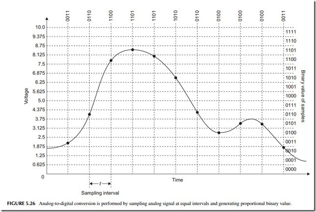
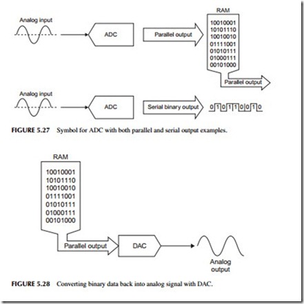
The process of converting an analog signal into a digital one is called analog- to-digital conversion, and it is performed by an analog-to-digital converter (ADC). The process, also referred to as sampling, is illustrated in Figure 5.26. The ADC looks at the analog input and periodically takes a sample of the volt- age at that instant, captures it, and then converts it into a proportional binary number. We say that we are digitizing the signal. The sample points are shown by the dots on the analog curve. The binary value of the sample is shown to the right of the curve. The conversion process actually results in a sequence of binary numbers that represent the analog waveform. These values are usually stored in a RAM or transmitted to other circuits as shown in Figure 5.27. Note the symbol for an ADC.
Digital-to-Analog Conversion
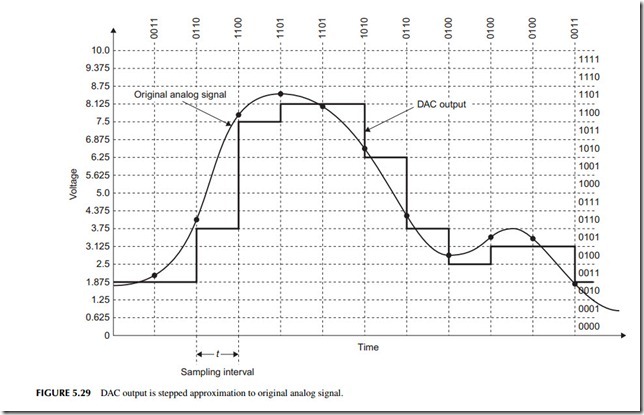
To recover the original signal, we put the data sequence previously captured by the ADC into a digital-to-analog-converter (DAC) (see Figure 5.28). The out- put is a version of the analog signal. The DAC output is not a perfect reproduc- tion, but just an approximation. This is shown in more detail in Figure 5.29. Each binary input results in a constant voltage output from the DAC during the sample period. The result is a stepped approximation to the original signal. The rate at which the binary data is sent to the DAC must be the same as the sampling interval to recover the original frequency information in the signal.
Resolution and Sampling Interval
The key to good data conversion is to use greater resolution and faster sampling rates. Resolution refers to the number of bits used in the data conversion.
In Figure 5.27, only 4 bits are used, so the resolution is poor. The voltage range is only divided into 16 intervals, meaning that amplitude variations at less than 0.625 volt are missed. This problem can be corrected by using more bits. ADCs are available in many bit sizes. The most common are 8, 10, and 12 bits, but 14 and 16 bits are available. Some methods of ADC produce resolutions of 20 to 26 bits. The result is a finer conversion of amplitude detail. As an example, if the 0- to 10-volt range in Figure 5.27 was sampled with a 12-bit ADC, the individual smallest voltage increment that can be detected is 10/212 = 10/4096 = 2.44 mV instead of the 0.625 volt in the figure.
Another critical specification is sampling rate. To retain all the frequency detail in a signal, the sampling rate must be at least twice the highest frequency in the signal. This is called the Nyquist criterion. For example, when digitizing music with a frequency range of 20 Hz to 20 kHz, the sampling rate must be at least double the 20-kHz frequency. In most systems, a rate of 44.1 kHz or 48 kHz is used.
ADCs with sampling rates to several hundred megahertz are commonly available, meaning that even radio signals can be digitized.


