Phase Splitters
In order to drive a pair of output valves in push–pull it is necessary to generate a pair of AC control grid drive voltages that are equal in magnitude but in phase opposition. The simplest way of doing this is to use a transformer as the anode load for an amplifier stage, but with a center-tapped secondary winding.
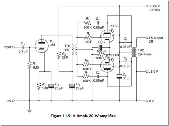
Figure 11.9 shows a typical center-tapped, transformer-coupled 20W audio amplifier, of the kind that would have been common in the period spanning the late 1930s to early 1940s. Because there are two coupling transformers in the signal path from the input and the LS output, which would cause substantial phase shifts at the ends of the audio spectrum, it would be impractical to try to clean up the amplifier’s relatively poor performance by applying overall negative feedback (from the LS output to V1 cathode) to the system.
Some local negative feedback from anodes to grids in V2 and V3 is applied by way of C4/R4 and C6/R7 in an attempt to reduce the third, and other odd-order, harmonic distortion components generated by the output valves. Since the designer expected that the output sound quality could still be somewhat shrill, a pair of 0.05-μF capacitors, C7 and C8, has been added across the two halves of the output transformer primary windings to reduce the high-frequency performance. These would also have the effect of lessening the tendency of the output valves to flash over if the amplifier was driven into an open- circuited LS load—an endemic problem in designs without the benefit of overall negative feedback to stabilize the output voltage.
The anode voltage decoupling circuit (R3, C3), shown in Figure 11.9, is essential to prevent the spurious signal voltages from the +V supply line to the output valves being introduced to the output valve grid circuits. This would, in the absence of the supply line decoupling circuit, cause the amplifier to oscillate continuously at some low frequency— a problem that was called motorboating, from the sound produced in the loudspeakers.
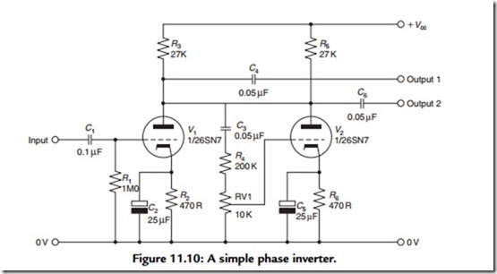
Various circuit arrangements have been proposed as a means of generating a pair of low distortion, low phase shift, push–pull drive voltages. Of these, the phase inverter circuit of Figure 11.10 is the simplest, but does not offer a very high-quality performance. It is, in principle, a bad thing to attenuate and then to amplify again, as is done in this
arrangement, because this simply adds just another increment of waveform distortion, due to V2, to that contributed by V1.
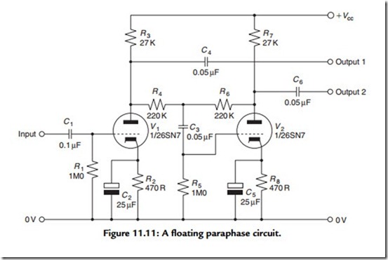
A much more satisfactory arrangement is that shown in Figure 11.11, in which V2 is operated as an anode follower, which, like the cathode follower, employs 100% negative feedback, although in this case derived from the anode. This stage contributes very little waveform distortion. Also, because both valves operate as normal amplifier stages, the available voltage from either output point will be largely unaffected by the operation of the circuit. An additional advantage over the circuit shown in Figure 11.10 is that the two antiphase output voltages are equal in magnitude, without the need to adjust the preset gain control, RV1.
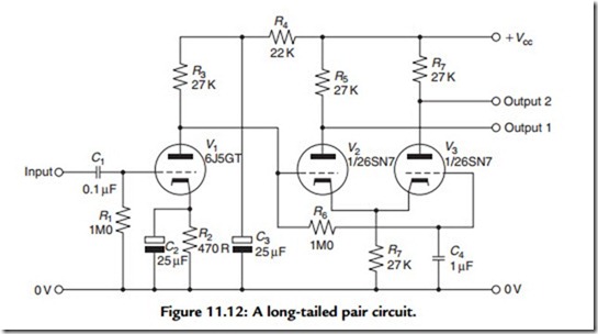
Another satisfactory circuit is that based on the long-tailed pair layout, in which, provided that the tail resistor is large in relation to the cathode source resistance (1/gm), the two antiphase anode currents will be closely similar in magnitude. The advantage of this circuit is that it can be direct coupled (i.e., without the need for a DC blocking coupling capacitor) to the output of the preceding stage, which minimizes circuit phase shifts, especially at the LF end of the passband. By comparison with the two preceding
phase-splitter circuits, it has the disadvantage that the available AC output swing, at either anode, is reduced greatly by the fact that the cathode voltages of V2 and V3 are considerably positive in relation to the 0-V line, which will almost certainly require an additional amplifier stage between its output and the input of any succeeding triode or beam-tetrode output stage.
This disadvantage is shared by the circuit layout shown in Figure 11.13, in which a direct-coupled triode amplifier is operated with identical value resistive loads in both its anode and cathode circuits. Because of the very high level of negative feedback due to the cathode resistor, both the distortion and the unwanted phase shifts introduced by this stage are very low. Significantly, this was the type of phase splitter adopted by D. T .N. Williamson in his classic 15-W audio amplifier design.


