Watch out for resonance when installing pump-motor drives
By RICHARD NAlLEN, P.E.
INSTALLATION of pump-motor drives often presents unusual and sometimes difficult mounting chal lenges. One such problem that can occur is mechanical resonance, some times called “tuning.” Resonance ap pears when the natural frequency of the vibrations of the drive-system structure or foundation is the same or very close to the drive operating fre quency, such as rotational speed. It is essential that the cause of this undesir able “tuning” be located and elimi nated before vibration builds to an excess, causing damage that could con ceivably result in total destruction of the drive.
A foundation may be “high-tuned” (natural frequency above running speed) or “low-tuned.” But if it natu rally vibrates right at running speed, trouble is inevitable. Would that be the motor’s fault? Not at all. However, because shutting off the motor makes the trouble disappear, engineers tend to lay the blame there immediately and wrongly.
Let’s consider some examples of the problem. First, look at a 300-hp pump drive in a particular paper mill. Severe vibration was causing frequent motor bearing failures. Plant engineers de cided that the application was “too demanding” for a standard motor, so they issued specs for a “special design” to cope with the condition. Only later did they study the drive with a vibra tion analyzer. This showed the motor was oscillating at one end at a natural frequency of 3600 Hz/min-the same as the drive speed. Reason: the base plate was inadequately grouted-in at one end. Once this was corrected, the trouble disappeared.
As a second example: six 150-hp pump motors were mounted on steel beams 5 ft above the plant floor. Seri ous noise and vibration plagued the installation. Rebalancing and replacing the motors produced no improvement . Finally, a test of the foundation struc ture showed that the beams were “tuned” to resonate at drive rpm.
Some engineers believe resonance can be eliminated as a drive problem by insisting on near-perfect balance of all rotating parts, so that if any vibra tion does appear later it must indicate a loss of balance that can be corrected. But such perfection is not attainable.
Structural resonance can be dealt with in only two ways. One solution to the problem is to “de-tune” the base using gussets, stiffeners, etc., to raise the natural frequency, or to cut away material or introduce spring washers in the motor mounting to lower that frequency.
A second solution can be to increase damping of vibrations by raising the mass of the drive. The vibrating struc ture represents work being done, because energy is required to move the parts. If more mass or inertia can be put into that vibrating structure, enough of the energy may be absorbed to limit the motion to harmless val ues.
Here’s an example of the addition of mass to the vibrating system-an effective cure- but certainly one to be avoided by proper initial design of the base structure. Several 3000-hp 1200- rpm pump motors were installed on vertical-pump heads after passing all factory tests. At startup, they vibrated as much as 17 mils. Lack of pump-head stiffness was the cause. To change the
assembled mass, shifting its natural vibration frequency as well as increas ing damping, operators stacked 3000 lbs of sandbags on top of each motor. Vibration then dropped to only one mil. Until this was done, it was difficult to believe that the base stiffness was the source of the problem.
Vertical pump motors
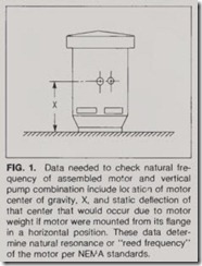
Such problems occur with a particu lar frequency on vertical-pump drives. Because the motor is attached to its base only at one end, it is free to shake at the other end, unlike a horiwntal motor with attachment points at both ends. But some pump drive specifiers have only recently begun to take into account the effect of how adding the motor alters the natural vibration fre quency of the assembly. To specify this equipment properly, request from the motor manufacturer the following data, as outlined in NEMA standards:
1. Motor weight.
2. Center of gravity location. This is the distance from the motor mounting flange to the center of gravity of the motor.
3. Motor static deflection. This is the distance the center of gravity would be displaced downward from its original position if the motor were horizontally mounted. This value assumes that the motor uses its normal mounting and fastening means but that the founda tion to which it is fastened does not deflect. See Fig. 1.
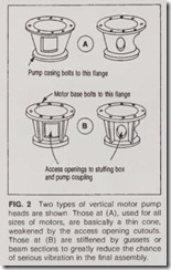
Another reason why vertical-pu mp heads are a frequent source of drive vibration is the type and number of cutouts in the head (Fig. 2). Cutouts are often provided in opposite sides for coupling access. These render the structure much less rigid in one plane than it is 90° away, giving the assembly two natural vibration frequencies in the two directions, one much lower than the other.
For example, the top-end vibration of one 800-hp, 1200-rpm vertical-pump motor was 30 mils in one direction and 13 mils 90° away. With the motor off the pump head, sitting on the floor, vibration did not exceed 2 mils in any direction. It was not feasible to stiffen the pump head. Instead, spring wash ers were used on the hold-down bolts to give the motor a “soft” mounting on the pump. This lowered the resonant frequency below operating speed fre quency, resul ing in assembled motor vibration of 6 mils maximum.
Pump heads tend to be of thin steel, with little reinforcement, even for large machines, apparently because designers feel the cylindrical shape will inherently be stiff enough. But this often is not the case. When you see pump heads such as shown in Fig. 2a, watch out. The use of stiffeners as shown in Fig. 2b is a great improve ment.
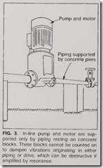
Even with a stiff support, vibration and even misalignment may be intro duced through connected piping. Bolted and welded couplings of various types can transmit pressure surges or reac tion forces into the drive. Consider the type of in-line pump shown in Fig. 3. Even slight vibration may set the assembly twangipg like a bowstring. Tho pipe is strong enough to support pump weight but is lacking in stiff ness.
More important, the attachment of heavy pipe-whether or not any fluid pulsation forces are present-can cause twisting or loosening of motor mount ings. In one instance, identical pump motors side by side were found to have entirely different vibration levels. One was satisfactory, the other dangerously high. Loosening individual bolts in the pump discharge line coupling was enough to make the high vibration vir tually disappear.
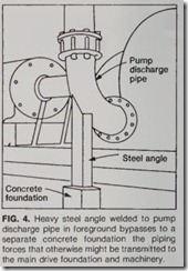
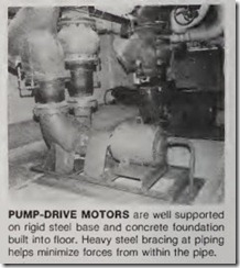
Fig. 4 shows a solution to this kind of problem. A heavy steel support was welded to the heavy discharge pipe to absorb the strong forces that occurred within the pipe. When any pump drive is being planned, piping forces should be carefully investigated.
Although small industrial motors are most often involved in foundation vibration problems simply because there are so many of them installed under such widely varying circum stances, larger and more costly rnachines are not immune .
