light–emitting Devices
Light-emitting devices produce light when subject to a current flow, converting electrical energy to light energy. A light-emitting diode (leD) is the most common semiconductor light-emitting device. Being a semiconductor component, it has an unlimited life span due to the absence of a filament, a cause of trouble in conventional lamps.
Any P–N junction diode can emit light when subject to an electrical current flow. The light is produced when the free electrons combine with holes, and the extra energy is released in the form of light. The frequency of the light emitted is determined by the type of semiconductor material used in construction of the diode. Regular diodes do not emit light because of the opaque material used in their packaging.
An LED is simply a P–N junction diode that emits light when a current flows through its junction. The light is visible because the LED is packaged in semitransparent material. The frequency of the light emitted depends on the material used in the construction of the LED. Gallium arsenide (GaAs) produces light in the infrared region, which is invisible to the human eye. Gallium arsenide phosphide
(GaAsP) emits a visible red light. By changing the phosphide content, different frequencies of light can be produced. LEDs are available in the following colors: infrared, red, orange, yellow, green, blue, ultra- violet, pink, purple, and white. The color of an LED is not determined by the color of the plastic lens but by the semiconductor material used to make it.
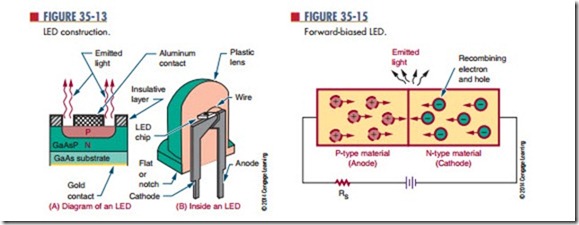
Figure 35-13 shows the construction of an LED. The P layer is made thin so that light energy near the P–N junction only needs to travel a short distance through it.
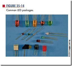
After the LED is formed, it is mounted in a package designed for optimum emission of light. Figure 35-14 shows some of the more common LED packages and colors. Most LEDs contain a lens that gathers and intensifies the light. The case may act as a colored filter to enhance the natural light emitted.
In a circuit, an LED is connected with forward bias to emit light (Figure 35-15). The forward bias must exceed 1.2 volts before a forward current can flow. Because LEDs can be easily damaged by an excessive amount of voltage or current, a series resistor is connected to limit current flow.
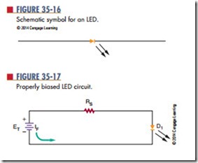
The schematic symbol for an LED is shown in Figure 35-16. Figure 35-17 shows a properly biased circuit. The series resistor (RS) is used to limit the for-ward current (IF) based on the applied voltage.
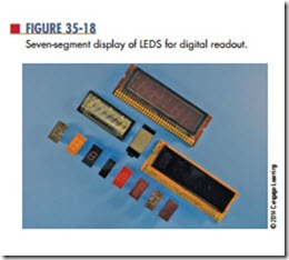
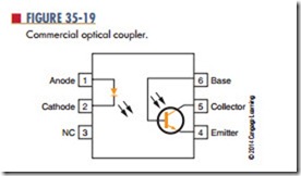
Figure 35-18 shows LEDs arranged to form a seven- segment display used for digital readouts. Figure 35-19 shows an LED used in conjunction with a phototransistor to form an optical coupler. Both devices are housed in the same package. An optical coupler consists of an LED and a phototransistor. The output of the optical coupler is coupled to the input using light produced by the LED.
The signal to the LED can vary, which in turn varies the amount of light available. The phototransistor converts the varying light back into electrical energy. An optical coupler allows one circuit to pass a signal to another circuit while providing a high degree of electrical insulation.
35–3 Questions
1. Explain how an LED differs from a conventional diode.
2. How does an LED emit different colors of light?
3. How may the LED package enhance the light emitted?
4. Draw and label the schematic symbol for an LED.
5. What is the function of an optical coupler?
