Portable instruments speed electrical troubleshooting
Two expert servicemen reveal how they use portable instruments to speed in-plant electrical troubleshooting.
FAST, efficient troubleshooting is vital to the continued success ofH. M. Davis & Sons, Inc., an appa ratus service firm of Bridgeton, N.J. The company specializes in the repair and rebuilding of electrical and me chanical equipment; however, trouble shooting and maintenance of in-plant equipment is an essential service pro vided to many of their customers.
The firm’s top field men are Bob Davis and Wayne Lang, who point out that proper use of portable test instruments is the key to effective troubleshooting. After years of expe rience they have found the most use ful instruments to be the multitester, the snap-around volt-ohm-ammeter, and the vibration analyzer/balancer. The following typical trouble calls show how they use these instruments.
Intermittent shutdown of exhaust fan motor
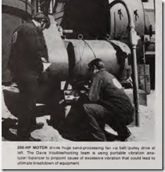
At a large sand-processing plant, a 200-hp, 460-volt induction motor driv ing a huge exhaust fan had been kick ing out intermittently, interrupting the continuous sand-processing oper ation. The resulting loss in production was costly, so plant management called in the Davis firm to solve the problem.
When Davis and Lang arrived at the plant, they first made a visual in spection of the motor, which was driv ing a large 6-ft-dia fan via a multiple belt drive. With the motor running, they checked the assembly for signs of malfunction, such as unusual noises, hot bearings, loose mounting bolts, slack belts, or any sign of acci dental damage to enclosures.
A similar inspection was made at the autotransformer-type reduced voltage motor controller. With the motor-circuit disconnect switch off and locked out, they checked for loose main fuseholders, for any darkened or burned spots, appearance of over load relays, condition of “start” and “run” contactors, and physical ap pearance of both line and control con ductors.
According to Davis, these inspec tions, which take only a few minutes, often indicate the source of the trouble. However, in this instance all components checked out OK. There fore, the next procedure is a check of circuit conditions using portable test instruments. First, the motor was started and the running current was measured using a snap-around amme ter. Davis emphasizes that common sense is important to obtain consist ently accurate readings with the snap-around ammeter. For example, be sure that stray magnetic fields do not affect the current reading. Ar range other conductors so that they are as far removed as possible from the conductor under test. If testing is being done at a control pan l, try to take the current readings at a loca tion remote from the relay magnet coils. For the same reason, avoid tak ing current readings on conductors at a point close to a transformer. All these influences can affect the ac curacy of the reading.
The motor running current in this case, as measured by the snap-around ammeter, was 265 amps. This was sig nificantly higher than normal (225 amps) and indicated an overload. This level of current could cause slow heat ing of the overload elements, and tripping could occur during a line voltage, switching or machine-start ing surge.
Before beginning the search for the overload, Lang suggested that the supply voltage be checked, since leads could easily be inserted into the am meter to permit it to be used as a voltmeter. This was quickly done and they proceeded, secure in the knowl edge that supply voltage was normal (460 volts, balanced on all three phases).
Davis and Lang explained that an overloaa (indicated by the higher than-normal current) is usually caused by a change in the driven load or a mechanical malfunction in the motor itself.
Because the load in this instance was a fan, it was unlikely that the load would be responsible for addi tional torque. On the other hand, the many components in the drive system suggested several possible sources of trouble. Lang explained that a bad bearing, bent shaft, misalignment of sheaves, or imbalance on the fan blades, shaft, or sheaves are common causes of overload on large complex machinery.
To quickly pinpoint this kind of problem, the Davis team uses a por table vibration analyzer/balancer. This compact instrument identifies vibrations and displays their ampli tudes and frequencies on meters when a cord-connected sensing head is in contact with the rotating appa ratus. The unit may be battery-oper ated or plugged into a 115-volt source. A series of curves furnished with the tester, on which vibration ampli tude is plotted against the frequency of vibrations, aid in diagnosing the conditions encountered. However, Davis is guided more by previous readings taken after the unit was aligned and balanced properly. Based on experience with similar equip ment, Davis points out that vibration amplitude should not exceed 2 mils at any of the measurement locations. (Other types of equipment may have limits as low as 0.1 mil, depending upon speed of rotation.)
The frequency of the vibration helps to pinpoint the source. For ex ample, a frequency equal to the rpm of the motor indicates that trouble could be caused by eccentric journals, misalignment, or a bent shaft. A fre quency twice the motor rpm indicates misalignment, rubbing, reciprocating forces, etc.
The vibration analyzer indicated an excessive vibration (4 mils) and that an imbalance somewhere in the fan blades was causing the problem. Us ing a vector analysis technique, Davis and Lang were able to pinpoint the exact location of imbalance on the 6-ft-dia multiple-blade fan and add weights in the proper location to pro vide a precision dynamic balance.
After this was done, proper read ings were obtained on the analyzer (less than 2 mils for a fan rotating at 750 rpm), and a check at the motor starter with the snap-on ammeter showed that motor running current was normal.
Troubleshooting control circuits
Davis and Lang agree that their multitester, sometimes called a mul timeter or volt-ohm-ammeter (VOM), is an especially useful instrument. This highly versatile tester is capable of measuring voltage, resistance, and low values of de current. Accuracy of the meter is dependent on the amount of current required to drive the pointer or needle full scale-the smaller the current, the more accu rate and sensitive the meter. Gener ally, sensitivity (which determines ac curacy) is expressed in ohms per volt.
This represents the impedance the meter presents to the circuit when used as a voltmeter. Multimeters are rated 1000, 5000 or 10,000 ohms per volt ac. Meters having a sensitivity of 10,000 ohms per volt have higher ac curacy because their higher imped ance creates less load on the circuit under test.
Davis emphasizes that safety must always be considered in the use of the multimeter. Know the voltage levels and shock hazards related to all equipment to be tested. Never try to take voltage readings on power dis tribution circuits rated over 600 volts. Measurement of high voltages is ac complished by installed instrument transformers and meters.
When making voltage measure ments on power and control circuits, be sure the meter selector and range switches are in the correct position for the circuit under test before ap plying test leads to the circuit conduc tors. To prevent damage to the pointer, always use a range that in sures less than full-scale deflection of the pointer. A mid- to %-scale deflec tion of the pointer assures the most accurate readings.
When operating the instrument as an ohmmeter, they find that it is par ticularly useful for checking de-ener gized control circuits and taking resistance readings of circuit camponents. These readings can be used later for comparison during trouble shooting.
The multitester proved its worth recently when Lang was called to solve a control circuit problem. The control system required that four mo tors start in sequence-t hat is, when start button No. 1was pressed, motor No. 1 would start; when start button No.2 was pressed, motor No.2 would start; etc. The scheme did not permit No.3 motor to be started before No.2, nor motor No.2 before No.1, etc.
In this instance, the operator was able to start motors No. 1 and 2 but when he pressed button No.3, motor No.3 would not start. When Lang ar rived at the plant, he made a visual exami nation of motor No. 3 and its starter. Both appeared normal. Then he obtained a schematic of the control system (see accompanying simplifi ed diagram). He noted that when push button No. 1 was pressed, coil No. 1 would energize, holding contact (1) closed to hold the coil energized, and line contacts to the motor would close, energizing the motor. In addition, coil No. 1 was furnished with an auxiliary contact (1A), which was wired in the start circuit to coil No. 2. This meant that the contact 1A had to be closed in order for current to flow through to coil No.2. A similar arrangement ex isted for the other circuits.
Now that he understood the oper ation of the control system, he natu rally directed his attention to the cir cuit supplying coil No. 3. He decided to make a voltage check of the circuit using his multitester (see diagram). First, motors No. 1 and 2 were started . Then, Lang checked to see if voltage was reaching the line side of start button No. 3 (test point A). Proper voltage was present here. With the operator holding the start button down, he checked for voltage at load-side terminal of the start but ton (test point B). This checked out OK. The circuit from the start button to contact 2A was brought to a termi nal block. A voltage check here (test point C) proved to be OK. Voltage also was present at both sides of the auxiliary contact 2A (test points D & E). From contact 2A to the coil No. 3, the circu it was routed through a ter minal block. At this location (test point F), h e could not obtain a voltage reading. Closer examination of the terminal point revealed heavy oxida tion and burned copper. The circuit was open at this point; thus, coil No.3 could not be energized to start motor No. 3. A n ew termination was made up and the system operated normally.
Lang explained that the probable cause was a loose connection which had existed from the time of original installation. A loose connection causes high resistance, which results in heat, expansion and contraction, more loosening, carbon buildup, and finally higher resistance and exces sive heat that causes complete de struction of the termination.
Checking circuits of process heaters
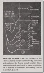
The multitester, used as an ohmme ter, is particularly useful in determin ing the condition of process heater circuits. In one typical application, strip heaters were installed in an en closed conveyor to heat materials as they were carried between buildings. Six heaters, with a total rating of 8100 watts, were connected in series and powered at 480 volts. After a pe riod of time, it was suspected that the heaters were not producing their full rated heat. Using the multitester, Davis first checked the supply voltage to the heaters at the control contac tor. The voltage supply measured 465 volts, which was considered adequate for proper operation. Then he decided to make a continuity check to see if the circuit was open or shorted at some point. A quick calculation indi cated that proper resistance of the circuit should be about 28 ohms plus a few ohms for conductor resistance, so Davis set the multitester to operate as an ohmmeter. A check at the con tactor showed an infinity reading, in dicating that the circuit was open at some point.
According to Davis, the fastest way to locate the open was to check the circuit continuity from its origin (con troller) starting at one leg and mak ing checks at each heater terminal in the series circuit. Because the control ler was located nearly 50 ft from the heater installation, he had to impro vise to create leads long enough to reach the points to be checked. He did this by attaching a 70-ft length of No. 14 THW copper wire to each multi tester lead. One lead was connected to one circuit leg at the controller (see diagram); the other was used as a probe lead. As shown in the diagram, he took measurements at point 1, where he obtained a proper reading of about 5 ohms; at test point 2, he ob tained a reading of approximately 10 ohms. At test point 3, the multitester showed a reading of infinity, indicat ing that the open was between test points 2 and 3. Suspecting that heater H3 was at fault, he checked across the terminals of the heater with the multitester still set to operate as an ohm meter and he obtained an infinity reading (open heater).
Next, he removed the faulty heater, installed a new one, and made a con tinuity check at the controller. The proper reading was obtained (approx-imately 28 ohms). To be certain that the circuit had not been grounded ac cidentally during testing, he checked resistance to ground with the multi tester set on its highest ohmmeter scale (R X 10). The reading was in finity, as it should be. Finally, he energized the circuit and took voltage readings. A copy of the recorded volt age, current and resistance readings was sent to the plant maintenance engineer for reference during future troubleshooting or preventive main tenance procedures.


