DEVELOPING CONTROL CIRCUITS
Circuit #1: Two Pump Motors
The water for a housing development is sup plied by a central tank. The tank is pressurized by the water as it is filled. Two separate wells supply water to the tank, and each well has a separate pump. It is desirable that water be taken from each well equally, but it is undesirable that both pumps operate at the same time. A circuit is to be constructed that will let the pumps work alter nately. Also, a separate switch must be installed that will override the automatic control and let ei ther pump operate independently of the other in the event one pump fails. The requirements of the circuit are as follows:
1. The pump motors are operated by a 480-volt three-phase system, but the control circuit must operate on a 120-volt supply.
2. Each pump motor contains a separate over load protector. If one pump overloads, it will not prevent operation of the second pump.
3. A manual ON-OFF switch can be used to control power to the circuit.
4. A pressure switch mounted on the tank con trols the operation of the pump motors. When the pressure of the tank drops to a certain level, one of the pumps will be started. When the tank has been filled with water, the pressure switch will turn the pump off. When the pressure of the tank drops low enough again, the other pump will be started and run until the pressure switch is satisfied. Each time the pressure drops to a low enough level, the alternate pump mo tor will be used.
5. An override switch can be used to select the operation of a particular pump, or to permit the circuit to operate automatically.
When developing a control citcuit, the logic of the circuit is developed one stage at a time until the circuit operates as desired. The first stage of the circuit is shown in figure 1. In this stage, a control transformer has been used to step the 480- volt supply line voltage down to 120 volts for use by the control circuit. A fuse is used as short circuit protection for the control wiring. A man ually operated ON-OFF switch permits the con trol circuit to be disconnected from the power source. The pressure switch must close when the pressure drops. For this reason, it will be con nected as normally closed. This is a normally closed held-open switch. A set of normally closed overload contacts are connected in series with coil 1M, which will operate the motor starter of pump motor #1.
To understand the operation of this part of the circuit, assume that the manual power switch has been set to the ON position. When the tank pressure drops sufficiently, pressure switch PS will close and energize coil 1M, starting pump # 1. As water fills the tank, the pressure increases. When the pressure has increased sufficiently , the pressure switch opens and disconnects coil 1M, stopping the operation of pump # 1.
If pump # 1 is to operate alternately with pump #2, some method must be devised to re member which pump operated last. This function will be performed by control relay CR. Since relay CR is to be used as a memory device, it must be permitted to remain energized when either or both of the motor starters are not energized. For this reason, this section of the circuit is connected to the input side of pressure switch PS. This addition to the circuit is shown in figure 2. When pressure switch PS closes and energizes motor starter coil 1M, all 1M contacts change position. Contacts 1M1 and 1M2 close at the same time. When 1M1
contact closes, coil CR is energized, changing the position of all CR contacts. Contact CR 1 opens, but the current path to coil 1M is maintained by contact 1M1• Contact CR2 is used as a holding contact around contact 1M2 .
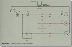
The next stage of circuit development can be seen in figure 3. In this stage of the circuit, motor starter 2M has been added. Notice that each mo tor starter coil is protected by a separate overload contact. This fulfills the requirement that an ov erload on either motor will not prevent the opera tions of the other motor. Also notice that this sec tion of the circuit has been connected to the
output side of pressure switch PS. This permits the pressure switch to control the operation of both pumps.
To understand the operation of the circuit, assume pressure switch PS closes. This provides a current path to motor starter coil 1M. When coil 1M energizes, all 1M contacts change position and pump #1 starts. Contact 1M1 closes and energizes coil CR. Contact 1M2 closes to maintain a current path to coil 1M. Contact 1M3 opens to provide in terlock with coil 2M, which prevents it from en ergizing whenever coil 1M is energized.
When coil CR energizes, all CR contacts change position. Contact CR 1 opens to break the circuit to coil 1M. Contact CR2 closes to maintain a current path around contact 1M1, and contact CR3 closes to provide a current path to motor starter coil 2M. Coil 2M cannot be energized, however, because of the now open 1M3 contact.
When the pressure switch opens, coil 1M will deenergize, permitting all 1M contacts to return to their normal positions, and the circuit will be left as shown in figure 4. Note that this diagram is intended to show the condition of the circuit when the pressure switch is opened-it is not intended to show the contacts in their normal deenergized position. At this point in time, a current path is
maintained to control relay CR When pressure switch PS closes again, con tact CR 1 prevents a current path from being estab lished to coil 1M, but contact CR3 permits a cur rent path to be established to coil 2M. When coil 2M energizes, pump #2 starts and all 2M contacts change position.
Contact 2M 1 opens and causes coil CR to de energize. Contact 2M2 closes to maintain a circuit to coil 2M when contact CR3 returns to its nor mally open position, and contact 2M3 opens to prevent coil 1M from being energized when con tact CR 1 returns to its normally closed position. The circuit will continue to operate in this manner until pressure switch PS opens and disconnects coil 2M from the line. When this happens, all 2M contacts will return to their normal positions as shown in figure 3.
The only requirement not fulfilled is a switch that permits either pump to operate independently if one pump fails. This addition to the circuit is shown in figure 5. A three-position selector switch is connected to the output of the pressure switch. The selector switch will permit the circuit to alter nate operation of the two pumps, or permit the operation of one pump only.
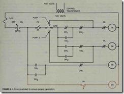
Although the logic of the circuit is now cor rect, there is a potential problem. After pump #1 has completed a cycle and the circuit is set as shown in figure 4, there is a possibility that con tact CR3 will reopen before contact 2M2 closes to seal the circuit. If this happens, coil 2M will de energize and coil 1M will be energized. This is of ten referred to as a contact race. To. prevent this problem, an OFF DELAY timer will be added as shown in figure 6. In this circuit, coil CR has been replaced by coil TR of the timer. When coil TR energizes, contact TR will close immediately, en ergizing coil CR. When coil TR deenergizes, contact TR will remain closed for one second before reopening and permitting coil CR to deenergize. This short delay time will ensure proper operation of the circuit.

![FIGURE-2-The-control-relay_thumb_thu[2] FIGURE-2-The-control-relay_thumb_thu[2]](http://machineryequipmentonline.com/electric-equipment/wp-content/uploads/2020/04/FIGURE-2-The-control-relay_thumb_thu2_thumb.jpg)

![FIGURE-4-Coil-CR-remembers-which-pum[1] FIGURE-4-Coil-CR-remembers-which-pum[1]](http://machineryequipmentonline.com/electric-equipment/wp-content/uploads/2020/04/FIGURE-4-Coil-CR-remembers-which-pum1_thumb1.jpg)
![FIGURE-5-The-basic-logic-of-the-circ[1] FIGURE-5-The-basic-logic-of-the-circ[1]](http://machineryequipmentonline.com/electric-equipment/wp-content/uploads/2020/04/FIGURE-5-The-basic-logic-of-the-circ1_thumb.jpg)
