Motor thermal protection minimizes downtime
Sensors ernbedded in motor winding s and placed in contact with bearing races reduce motor burnouts, eliminate nuisance tripping, extend motor lif e, and minimize equipment shutdowns.
WINDING burn outs, nuisance shut downs, an d bea ring failures are among th e majo r m otor problems which plagu e indu stry with f requent reoccurr ence. In most in stan ces, these can be traced to con dition s resulting from improp er mot or control an d op eration. This n eed n ot occu r; inherent thermal prot ect ion systems are avail able which can safely and accurately limit motor temperatures to accept abl e levels even un der abn ormal operating condition s.
Motor failures cau se costly, un scheduled equipm en t down ti m e. W ith mat erial and labor costs on the rise, it becomes mandat ory that all available means be used to k eep equipm en t op erating at maximum efficiency. Downtime production losses on a typ ical automatic transf er line have bee n known to cost $1500 per minu te, ex cluding normal maint enance costs for repair of the fault. Even in less criti cal operation s, th e cost of equipment downtim e b ecom es prohi bitive when extended beyo nd an hour or two.
Downtim e periods are of two general types: those that occur du e to m o tor failure such as bearing seizure or motor winding burnout , and those re sulting from t emporary shutd own due to operation of a protection sys tem. Although both occur with regu larity in many industries, they are not always systematically recorded to provide m eaningful comparisons. For example, moto r winding burnout usu ally is mor e noteworthy, since a ma chi ne operation is stopped and several people become im·olved in restoring the equipment to proper running or der. In these instances, documenta tion is usually more complete regard ing the nature of the fault, its corr ection, and subsequent production loss.
This is not necessarily true where equipment is shut down due to oper ation of a protective device. Even though equipment damage generally is avoided or postpo n ed, repeated downtime over a pe riod of months can actually amount to a greater total than for motor burnout conditions. Because these shorter downtime peri ods are not normally recorded, their cumulative total is not always cor rectly assessed by management. Fur thermore, much of this downtime is of the nuisance variety and could be avoided with proper protection sys tems. It follows that more effective motor protection could provide a solu tion to both classes of equipment downtime.
Why motors overheat
Commo n causes of motor over heating include excessive over loading, bea ring seizure and misalignment. However, there are several less dramatic effects which contribute heavily toward motor failure. These include:
1. Slight but sustained running overloads
2. Rapid load fluctuations (jog- ging and plugging)
3. Restricted ventilation
4. Locked rotor
5. Single phasing on three-phase systems
6. High ambient temperature
7. Excessive duty cycles
8. Excessive load inertia
9. Improper motor-load match
10. High altitude
11. Power supply variations (high or low voltage, unbalanced voltage)
In all of these instances, the end re sult is higher-than-normal winding temperatures which, if continued, will result in reduced motor life. A further complication is the trend toward re duction in size and lowering of cost in motor design. Because motor manu facturers are utilizing superior insu lating materials, and because motors themselves are being allowed to oper ate at higher temperature limits, the margin of safety is being narrowed. Becaus·e the heart of any motor is its winding, excessive temperatures in this region can promote rapid and irreversib le damage. As a r u le of thumb, it has bee n determined that for approximately every 10-deg C in crease in winding temperature, the useful life is halved. Thu s, it becom es essential to limit the winding tem perature to safe levels during abnor mal operating con ditions to assure full motor life.
Motor protection criteria
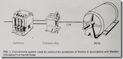
Section 430 of the NE Code provides for motor and bran ch-circu it protection. Article 430-32(a)(l) de scribes a system using motor curren t as a means of provid ing an an alog of the motor’s temperature . Fig. 1 illu s trates this system in pictorial fashion . Although overcurrent systems of various types have been used for many years, their analog natu re is not capable of accurately reproducing the temperature conditions of tod ay’s modern motors. In most instan ces an adverse change in a motor’s tem pe ra ture condition is caused by in creased current. If an overcurrent device is used, this change is interpreted as an increase in temperature, and the m o-” tor is shut down at some point in time.
However, not all factors in flu en c ing excessive motor temperat ure are reflected by increased motor current . Notably in this category are restric tions in motor ven tilation an d in creases in altitude. The in ability to detect these condit ion s, especially blocked ventilation, seriously compro mises the protection needed to reduce the incidence of motor burnout and equipment downtime.
Heating and cooling rate considerations
A further difficulty encountered with devices which analog motor tem pe rature through current sensing is the m atter of different heating and cooling rates between th e motor and the protective device. Since a single overload relay with chang es in heat ers can be used to protect a number of m otor sizes, it is practically impos sible to achieve a close thermal match on each motor be ing protected. The m otor with the larger thermal mass is pron e to heat and cool at rates which are different from the overload relay. Depen din g upon th e nature of the motor ‘s overloaded condition , this characteristic can cause either nui sance tri pp ing or premature motor failure. The f ormer can be caused by slight and sustained running overload resul ting in operation of the over current r elay bef ore the motor wind ing reaches abnormal temperatur es. The effect of these nuisance trips of ten prom otes arbitrary upward cali bra tion changes in the level of protec t ion to a void nuisance operation. Premature m otor failure can result f rom repetitive resetting of an over load relay under heavy overload or locked-rotor conditions. Because the overload relay’s current-sensing mechanism can cool at a faster rate than the motor, it usually can be reset before the motor has had sufficient time to cool.
Effects of ambient temperature
Analog temperature protection by overcurrent m eans also suffers from diff erences in ambient temperature betwe en the motor and controller sites. Since thermally activated over load relay s are generally affected by their immediate environment, any changes in the ambient temperature due to ventilation or proximity to other controls and heat sources will aff ect the level of motor protection. Again, depending on the location of the motor and its condition of over load, the protection system can cause either nuisance tripping or premature winding burnout.
An overload relay located in a non ventilated cabinet can cause prema ture motor shutdown unless suitably compensated. A hotter ambient at the controller site effectively lowers the prot ection point , shut ti ng th e motor down prematur ely. Conv ersely, if the motor is locat ed n ear a source of hea t , such as a furnace, th e safe tempera ture could be exceeded before its cur rent reach es th e level w h ich activates the overload rel ay.
Since ambien t tempe rature condition s in control pa n els va ry consider ably due to season al changes, venti lating eff ective n ess, and other pm duction relat ed reason s, it is not prac tical in most cases to compensate th ese d evices every ti m e a chan ge oc curs. A s a con seq u en ce, the degree of overtemperature protection to a mo tor will be subject to th e prevailing ambient condit ion s.
Integral protection
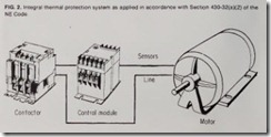
Section 430-32(a)( 2) of the NE Code mak es pro v ision for a n alt er nate form of motor and bran ch-circu it pro tection -the u se of th ermal protectors integral with the m otor itself. Such prot ection mak es it po ssibl e to sense all stator winding overtemperature condition s, including those resultin g from block ed ventilati on and ambien t conditions. One f orm of this system
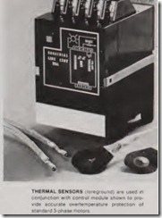
uses integrally installed thermal sen sors in the motor winding with a panel-mou n ted control module.
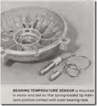
I n accordance with the provisions of Section 430-32(a)(2), this system, wh en approved for use wit h the motor w hich it protects, also provides pro tect ion to the controller and branch circuit conductors against excessive heati n g due to motor overloads or f ailu re to start. Fig 2 shows the com pon ents of a typical system using thermal sensors both in the motor an d in a companion control module. The small size and fast response of th ese sensors enable them to follow even the higher rates of temperature rise experienced with today’s T frame motors. Bearing-overtemper ature sensors are also available and can be used with the same control module.
Of the various types of sensors available, those having abrupt changes in resistance at the tempera tu re trip point offer several advan tages. In addition to being available in numerous temperature values, they can be series-connected (up to three) wit h in a motor, requiring just two leads back to the control module. Since the module is not required to make a qualitative judgment on each set of sensors, different temperatures can be used without the need for re calibration. A module with three sen sor inputs could, for example, accom modate three motors each protected to different temperature levels. Also, it is possible to intermix series sen sors of different temperature set points on a single input channel, since any sensor experiencing a high resist ance will trip the control module.
Protection of a motor based on the actual thermal conditions existing within the stator winding is a feature which overcomes many of the prob lems p revalent with conventional overcu rrent systems. Advantages in clu de:
1. Protects against motor winding overtempe rature, regardless of the factors responsible for the over tempe rature condition.
2. Reacts to motor winding tempe rature only and is insensitive to temperature con ditions at the motor controller.
3. Acts upon total temperature of the winding, factoring in the contri bution of ambient to total tempera ture.
4. Prevents reset of the protective system until there is assurance that motor temperature has dropped to a safe value.
3. Permits remote reset by oper ating personnel just as soon as safe conditions have been restored at the motor; does not require a qualitative judgment to be made as to whether motor has cooled down sufficiently.
4. Retains an “overload trip” flag for information of troubleshooters when system has been reset by oper ating personnel.
5. Has built-in, inherent fail-safe protection against short circuit, open circuit and loss of control po ver.
6. Is tamperproof and cannot have trip point altered by simple ad justment or component replacement at the controller.
7. Utilizes a single, versatile, basic module that can be used to protect most motors of any size in the plant.
8. Can use a single module to handle multiple in puts from several motors if motors are interlocked with each other, lowering “cost per motor” of protection. Each input to the sen sing module can be different and matched to the temperature with stand of its specific motor.
11. Can be easily retrofitted to pro tect most existing motors in a plant.
Most nuisance-type downtime is eliminated with inherent thermal protection systems. Since a motor is taken off the line only when its actual protection level is exceeded, any trip is a “necessary trip” rather than a nuisance one. Because effective locked-rotor protection is achieved by close thermal coupling between the motor winding and the sensing sys tem, the machine operator cai1 be allowed to reset and restart his own equipment safely where faults can be removed easily. The electrician at his option can still investigate the faulted condition- but later, during a noncritical period. Freeing him and other maintenance personnel to work on “real” problems is perhaps one of the greater cost-saving benefits to be realized with inherent thermal pro tection systems.
Installation
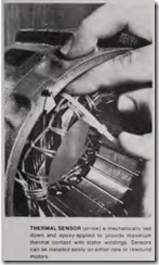
It is relatively easy to add over temperature protection to most exist ing industrial motors. It is even easier to install these sensors at the time a motor requires rewinding, before varnish dip-and-bake operations.
The materials and construction of these sensors make them capable of withstanding the handling and high temperature bake procedures in volved in motor rewinding. Also, the encapsulating materials have been specifically selected to resist deterio ration from exposure to common in dustrial environments, such as heat, varnish, moisture, oil and other con taminants.
Sensors can provide overtempera ture protection for both running overload and locked-rotor conditions. Considering running overload first, the sensor operating temperature should be above the maximum rated motor design temperature and below the maximum allowable winding ternperature limit. When sensor tempera ture is selected close to the maximum normal motor design temperature taking into account the sensor/ system tolerances-motor life is en hanced, and temperatures on locked rotor remain within allowable limits for most induction motors rated 600 volts or less.
Although the sensors can protect for both running-overload and locked rotor conditions, the existing over current devices should be retained in retrofit applications to ensure com pliance with the motor branch-circuit protection requirements of the NEC. For a typical general-purpose Class B motor, a sensor with a nominal operating temperature of 145C is indi cated. This is arrived at by providing for a tolerance of plus or minus 5 deg C for the protection system and a margin of 10 deg C over the max imum design operating temperature of 130C, which is at 1.15 service factor load for this rating. The purpose of this margin is to insure against nui sance tripping of the protection sys tem. At the same time, the maximum sensor (high-side tolerance) limits motor temperature to 150C, which is well below the recognized limit of 165C for running overload. In most retrofit applications, it will be pos sible to use a single sensor tempera ture for a given insulation system.
