Psychoacoustic Masking Systems
Wideband compansion systems view the phenomenon of masking very simply and rely on the fact that program material will mask system noise. But, actually masking is a more complex phenomenon. Essentially it operates in frequency bands and is related to the way in which the human ear performs a mechanical Fourier analysis of the incoming acoustic signal. It turns out that a loud sound only masks a quieter one when the louder sound is lower in frequency than the quieter, and only then, when both signals are relatively close in frequency. It is due to this effect that all wideband compansion systems can only achieve relatively small gains. The more data we want to discard the more subtle must our data reduction algorithm be in its appreciation of the human masking phenomena. These compression systems are termed psychoacoustic systems and, as you will see, some systems are very subtle indeed.
MPEG Layer 1 Compression (PASC)
It’s not stretching the truth too much to say that the failed Philips’ digital compact cassette (DCC) system was the first nonprofessional digital audio tape format. As we have seen, other digital audio developments had ridden on the back of video technology. The CD rose from the ashes of Philips Laserdisc, and DAT machines use the spinning- head tape recording technique originally developed for B and C-Format 1-inch video machines, later exploited in U-Matic and domestic videotape recorders. To their
credit then, that, in developing the DCC, Philips chose not to follow so many other manufacturers down the route of modified video technology. Inside a DCC machine, there’s no head wrap, no spinning head, and few moving precision parts. Until DCC, it had taken a medium suitable for recording the complex signal of a color television picture to store the sheer amount of information needed for a high-quality digital audio signal. Philips’ remarkable technological breakthrough in squeezing two high-quality, stereo digital audio channels into a final data rate of 384 kBaud was accomplished by, quite simply, dispensing with the majority (75%) of the digital audio data! Philips named their technique of bit-rate reduction or data-rate compression precision adaptive sub-band coding (PASC). PASC was adopted as the original audio compression scheme for MPEG video/audio coding (layer 1).
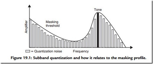
In MPEG layer 1 or PASC audio coding, the whole audio band is divided up into 32 frequency subbands by means of a digital wave filter. At first sight, it might seem that this process will increase the amount of data to be handled tremendously—or by 32 times anyway! This, in fact, is not the case because the output of the filter bank, for any one frequency band, is at 1/32nd of the original sampling rate. If this sounds counterintuitive, take a look at the Fourier transform and note that a very similar process is performed here. Observe that when a periodic waveform is sampled n times and transformed, the result is composed of n frequency components. Imagine computing the transform over a 32- sample period: 32 separate calculations will yield 32 values. In other words, the data rate is the same in the frequency domain as it is in the time domain. Actually, considering that both describe exactly the same thing with exactly the same degree of accuracy, this shouldn’t be surprising. Once split into subbands, sample values are expressed in terms of a mantissa and exponent exactly as explained earlier. Audio is then grouped into discrete time periods, and the maximum magnitude in each block is used to establish the masking “profile” at any one moment and thus predict the mantissa accuracy to which the samples in that subband can be reduced, without their quantization errors becoming perceivable (see Figure 19.1).
Despite the commercial failure of DCC, the techniques employed in PASC are indicative of techniques now widely used in the digital audio industry. All bit-rate reduction coders have the same basic architecture, pioneered in PASC: however, details differ. All
systems accept PCM dual channel, digital audio (in the form of one or more AES pairs) is windowed over small time periods and transformed into the frequency domain by means of subband filters or via a transform filter bank. Masking effects are then computed based on a psychoacoustic model of the ear. Note that blocks of sample values are used in the calculation of masking. Because of the temporal, as well as frequency dependent, effects of masking, it’s not necessary to compute masking on a sample-by-sample basis. However, the time period over which the transform is performed and the masking effects computed are often made variable so that quasi-steady-state signals are treated rather differently to transients. If coders do not include this modification, masking can be predicted incorrectly, resulting in a rush of quantization noise just prior to a transient sound. Subjectively this sounds like a type of pre-echo. Once the effects of masking are known, the bit allocation routine apportions the available bit rate so that quantization noise is acceptably low in each frequency region. Finally, ancillary data are sometimes added and the bit stream is formatted and encoded.
Intensity Stereo Coding
Because of the ear’s insensitivity to phase response above about 2 kHz, further coding gains can be achieved by sending by coding the derived signals (L + R) and (L – R) rather than the original left and right channel signals. Once these signals have been transformed into the frequency domain, only spectral amplitude data are coded in the HF region; the phase component is simply ignored.
The Discrete Cosine Transform
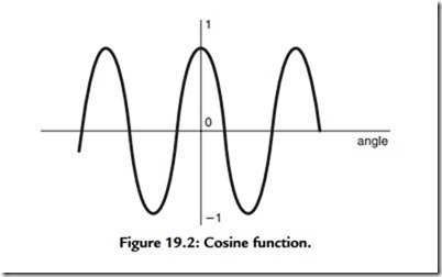
The encoded data’s similarity to a Fourier transform representation has already been noted. Indeed, in a process developed for a very similar application, Sony’s compression scheme for MiniDisc actually uses a frequency domain representation utilizing a variation of the discrete fourier transform (DFT) method known as the discrete cosine transform (DCT). The DCT takes advantage of a distinguishing feature of the cosine function, which is illustrated in Figure 19.2, that the cosine curve is symmetrical about the time origin. In fact, it’s true to say that any waveform that is symmetrical about an arbitrary “origin” is made up of solely cosine functions. This is difficult to believe, but consider adding other cosine functions to the curve illustrated in Figure 19.2. It doesn’t matter what size or what period waves you add, the curve will always be symmetrical about the origin. Now, it would obviously be a great help, when we come to perform a Fourier transform, if we
knew the function to be transformed was only made up of cosines because that would cut down the maths by half. This is exactly what is done in the DCT. A sequence of samples from the incoming waveform is stored and reflected about an origin. Then one-half of the Fourier transform performed. When the waveform is inverse transformed, the front half of the waveform is simple ignored, revealing the original structure.

