Checking capacitor motors
A systematic analysis of the circuits and components of these popular motors, together with a few simple tests, can greatly simplify troubleshooting.
By J. L. WATTS, A.M.I.E.E.
Southampton, England
THE FAILURE of a capacitor motor to start or function properly does not necessarily indicate a defective winding. Other components coul d be at fault. These include defective starting relays or switches or their mechanisms, faulty capacitors or autotransformers, loose connections at built-in thermal overload devices, and bad bearings on the motor or the load it drives.
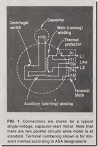
Faulty motors should be checked systematically to pinpoint the trouble quickly. In general, there are two par allel circuits through a capacitor mo tor at standstill, so there should be a noticeable hum when the motor is switched on. If no hum exists, the first obvious check is to be certain that the bran ch-circuit protective de vices or control switches are not open. Th e next step is to connect a test lam p across the line terminals of the motor (P1 and T4 in Fig. 1). If the lamp fails to light, there is an open circuit in the su pply to the motor. The motor shoul d f unction properly once the open has been locat ed and cor rected. However, if the lamp lights (on term inals P1 and T4) but the mo tor doesn’t hum , th e cause is either a break in the line conductors insid e the motor or an open circuit in both the starting and running circuits. The most likely point of such an internal open circuit is a thermal protector with open contacts due to over heating or faulty starting. Some pro tectors may reset automatically after cooling down; others may have to be reset manually. Another cause of in ternal open circuits could be faulty thermal protector contacts or connec tions indicated by failure of a test lamp ·to light when connected across terminals T1 and T4.
Improper starting under load
If the motor hums but refuses to start or start properly when ener gized, the supply voltage may be low, or a dual-voltage motor might be im properly connected with its windings in series on the lower voltage of its range. Obviously, wrong hookups would be suspected only at the initial startup. If the line voltage and con nections are in order, the motor should be uncoupled from the drive and energized at no load. If it starts correctly, faulty starting on load may be due to (1) overload, (2) a ground fault or short circuit in the windings,
(3) a defective capacitor or autotrans former, or (4) an open circuit in the starting capacitor of a two-value ca pacitor motor. A motor also could start properly unloaded but fail to start under load if the bearings are badly worn and cause the rotor to rub on the stator core.
If the rotor clears the stator core and the motor is self-starting when operated unloaded, its performance should be observed. If it shows signs of overheating in a short time, it should be turned off. Contacts of a starting rela y or centrifugal switch sticking in th e closed position could cause the overheating. If so, the over heating should cease after one lead of the starting winding is disconnected after the motor is started and up to speed. Replacing the switching mech anism should correct the problem.
Overheating of an autotransformer used with some two-value capacitor motors may be due to a short circuit in the capacitor or a short circuit or ground fault in the autotransformer. One of the latter two would be indi cated if the overheating continued af ter disconnecting the capacitor.
Testing windings
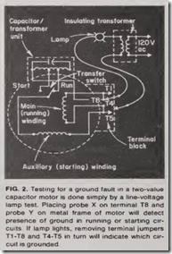
If the motor overheats when run ning at no 18ad, after one lead of the starting winding has been discon nected, a ground f ault or short circuit in the windings is indicated. To test for a ground fault, a line-voltage test lamp and a 1:1 double-wound trans former may be used as in Fig. 2. To test for a short circuit between ma in an,9 auxiliary stator windings, th e two windings ma y be disconn ected from each other and the test prob es X and Y applied to one end of each of the two winding s. To t est f or a short circuit in a main w inding , the de resistance of similar section s of th e windings can be measured and com pared-a relatively simple ma tter with a dual-voltage motor. U n equal resistances in similar sections indi cate a short circuit.
A two-value capacitor motor with an autotransformer ma y fail to start loaded and yet may start unload ed if the starting capacitor is open-cir cuited. In this case, it is proba ble that starting will be improved if th e ca pacitor is bridged by a lamp or shorted by a piece of wire. Other ca pacitor motors ma y start properly only on no load if th e starting capaci tor is shunted. For these, start ing may be improved if the capacitor is disconnected and the extern al leads of the capacitor are bridged by a suit able lamp. A short circuit in a n elec trolytic capacitor may be indicated by the top of the capacitor havin g bee n blown off by a rise in internal pres sure.
Checking capacitors
A capacitor may be t ested for a short circuit by conn ecting it across the ac supply for a few secon ds through a fuse rated slightly over the normal capacitor current. The fuse will open if the capacitor is shor t-cir cuited. On a 110-volt, 60-cycle supply, the normal current of a capacitor m ay be considered as 0.4 amp per 10 micro farads, or 0.8 amp per 10 microfarads on a 220-volt, 60-cycl e supply.
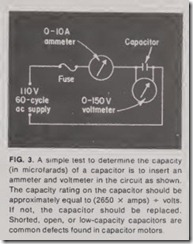
However, a bett er test for an open circuit, short circuit , or loss of capaci tance (as can occur if the electrolyte in an electrolytic capacitor dries out) is shown in Fig. 3. In this t est , th e ca pacitor should be energized j u st long enough to take quick voltage an d am pere readings, because a capacitor of this type is designed only for in ter mittent duty. On a 60-cycle ac supply, the capacitance in microfarad s may be taken as equal to (2650 X am ps) + volts. This calculation should be compared to the value marked on the ca pacitor. Any replacement capacitor should be approximately the same rating as the original one to insure the required starting torque.
Failure to start atnoload
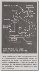
If a motor hums but fails to start when switched on unloaded, the start ing capacitor should be bridged by a lamp or, momentarily, by a piece of wire. If this starts the motor, there is an open circuit in the capacitor. If it does not start the motor, the rotor should be spinned rapidly by hand and the motor then turned on. It probab ly will accelerate in the direc tion it has been turned. If it runs up to full speed in a normal manner, an open circuit in the starting circuit should be suspected. But if the motor reaches only about % normal speed, the ru nning winding has an open cir cuit. Fig. 4 shows a method of using the test set in checking for an open starting circuit. The same method can be used to check for an open circuit in the main winding. Note that the two wind ings must be disconnected from each other for these tests, and the ca pacitor must be bridged when testing the starting winding circuit.
An open in the starting winding circuit often is due to the contacts of a centrifugal switch or starting relay not closing properly at starting. This would be confirmed if the motor started properly on ly when these con tacts were bridged by a piece of wire. Where there is excessive end play in the rotor, the motor may stop at times if the centrifugal device moves away from the contacts mounted in side the motor case. Such a condition may not permit the contacts to close once the motor returns to standstill. In this event, the trouble may be overcome by fitting washers onto the shaft in order to take up excessive end play.
An electromagnetic starting relay must be adjusted to close its contacts when the motor is turned on at rest with the minimum supply voltage likely to be experienced, a;,d to open its contacts as the motor approaches its working speed-even when driving its rated load with maximum and minimum values of anticipated sup ply voltage.
If a motor overheats on load, it may be due to overload, low voltage, one or more windings shorted or grounded, an open-circuited winding in a dual voltage motor operating on the lower voltage, incorrect connections of a dual-voltage motor, a short-circuited capacitor of a permanent-capacitor motor or a two-value capacitor motor, or faulty contacts of a centrifugal switch or starting relay. A systematic approach to the problem will uncover the defect as indicated by the pre viously described tests.


