Direct- Current Armature Windings
Armature windings can be divided into two general classes according to the methods of connecting the coils to the commutator. They are called lap windings and wave windings, the names of which are derived from the appearance of the coils when they are traced through the winding.
LAP WINDINGS AND WAVE WINDINGS
Figure 7-1 shows a section of a lap winding. Starting with the coil at the left, trace the path of current through this coil as shown by the arrows and then on through the next coil, etc., until the end of the circuit is reached. You will find all the coils to be alike, but to clarify matters, the coil to the extreme left is drawn with heavier lines to make the tracing easier. Note that each coil overlaps the next as it is traced-thus the name lap windings, since the coils overlap.
The winding in Fig. 7-2 is the wave type. Again, start at the left and trace the path of current through the two coils shown by the heavy lines. Note the location of the north and south field poles, which are shown by the dotted rectangles and marked N and S. In tracing the circuit through, it can be seen that each coil in this circuit is separated from the last by the distance of one pair of poles, which gives a wave-like appearance of the two coils traced in the heavy lines; from this appearance comes the name wave winding.
A lap winding is a parallel winding with an even number of segments and slots. The number of bars, however, is equal to, or a multiple of, the number of slots- depending on the number of coils per slot. The term parallel winding comes from the fact that there are as many circuits in parallel as there are poles. Thus, a four-pole motor has four circuits in parallel and a six-pole motor has six circuits in parallel through the ar mature. This requires the same number of brushes as there are poles for the motor.
Since there are so many paths in parallel in a lap winding, a large amount of current can pass through the winding. This, in turn, reduces the amount of voltage needed in the armature to “push” the current through so many paths.
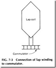
The lead connections for a lap winding come from each side of the coil as top and bottom leads and connect adjacent to each other on the commutator. The position that they connect on the commutator cannot be set down to a hard and fast theoretical rule but is at the discretion of the manufacturer who designs a certain motor.
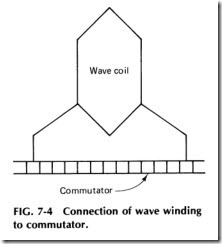
There are three groups of wave winding, namely, simplex wave winding, duplex wave winding, and triplex wave winding. Wave windings are known as series windings and are generally used for motors of higher voltage and smaller currents.
Both lap and wave windings are used in armatures from fractional horsepower sizes to those of hundreds of horsepower. The type of winding selected by the motor designer depends on several factors in the electrical and mechanical requirements of the machine. Wave windings require only two brushes on the commutator, while lap windings have as many
brushes as there are field poles. The wave winding permits the brushes to be located at adjacent poles and also on whichever side of the commu tator they may be most convenient and accessible for inspection and repairs.
The major differences between lap and wave windings include the following:
1. A lap winding has half the voltage rating of a wave-wound armature, wound identically, and therefore can carry much more current through it.
2. The span of the leads of a lap winding, being adjacent, is not dependent on the number of poles, as is the lead span of a wave winding, where the leads are widely separated.
3. In a wave winding there are only half as many brushes as there are in a lap winding because the current has only half as many paths.
An armature winding is an electromagnet having a number of coils connected to commutator bars. There must be at least one start and one finish lead connected to each commutator bar. The coil leads of a lap wound armature connect to commutator bars that are near each other, and the coil leads of a wave-wound armature connect to commutator bars that are widely separated. See Figs. 7-3 and 7-4.When current flows through the coil in a clockwise direction, a southpole will be produced on the surface of the armature. If the current flows in a counterclockwise direction, a north pole will be produced on the sur face of the armature. A large number of coils are used to produce a strong magnetic pole and a smoother twisting action.
Although there are only two types of de armature windings, there are a number of winding connections that apply to either a lap- or a wave wound armature.
SYMMETRICAL AND NONSYMMETRICAL CONNECTIONS.
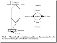
If the coil leads connect to commutator bars that are on a line with the center of the coil, the connection is symmetrical (Fig. 7-5). If the coil leads
connect to commutator bars that are not on a line with the center of the coil, the connection is nonsymmetrical (Fig. 7-6).
The brushes must always short the coil when it is in the neutral plane, which means that the brushes must be located on a line with the center of the field pole if the coil is connected symmetrically and located between the field poles if connected nonsymmetrically.
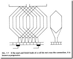
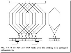
PROGRESSIVE AND RETROGRESSIVE CONNECTIONS. If the start and finish leads of a coil, or the element of a coil, do not cross the connection, it is known as progressive as shown in Fig. 7-7. If the start and finish leads of a coil, or the element of a coil, cross the winding, it is connected retrogressively. See Fig. 7-8.
If a winding is changed from progressive to retrogressive or vice versa, the effect will be reversed rotation of a motor and reversed brush polarity on a generator. Lap-wound armatures are usually connected pro gressively and wave-wound armatures retrogressively.
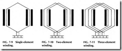
ELEMENT WINDINGS. Element windings are used to reduce the voltage across adjacent commutator bars and decrease the tendency of brush sparking. Example: An armature has 30 turns/coil, and the volt age per turn is 1or 30 V/coil. If the coil is wound in one section and con nected to adjacent commutator bars, the voltage across the bars will be 30 V. Such a coil would have one start and one finish lead, and there would be as many bars as slots. This would be a single-element winding as shown in Fig. 7-9.
If this coil were divided into sections (15 turns/section) and each sec tion were connected to adjacent bars, the voltage across adjacent bars would be 15 V. Such a coil would have two start and two finish leads, and there would be twice as many bars as slots. This would be known as a two-element winding as shown in Fig. 7-10.
Should the coil be divided in three sections (10 turns/section) and each section connected to adjacent bars, the voltage across adjacent bars would be 10 V. Such a coil would have three start and three finish leads, and there would be three times as many bars as slots. This would be known as a three-element winding. See Fig. 7-11.
Element windings are particularly desirable for high-voltage ma chines. The practical limit is usually three or four elements. On high voltage machines the voltage between bars usually does not exceed about 25 V. On smaller machines it may range form 2 to 10 V. Therefore, the higher the voltage the machine is to be operated at, the greater number of commutator bars it will usually have.
The number of slots in an armature is determined by the number of poles and the practical number of slots which can be used per pole. The slots, of course, cannot be too numerous or close together, or there will not be sufficient iron between the coils to provide a good magnetic path through the armature for the field flux.
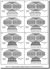
The number of slots is generally considered in determining the exact number of commutator bars, as the number of bars is usually a multiple of the number of slots. For example, an armature with 24 slots might have 24, 48, or 72 commutator bars. In the last case the coils would be wound with three conductors in parallel, and the six leads from each coil would be connected to the proper bars.
Armature windings, therefore, can be called single-element, double element, or three-element windings according to the number of conductors in parallel in the coils and the number of bars in proportion to the number of slots.
ARMATURE EQUALIZER CONNECTIONS
Equalizer connections provide better commutation, make possible one half of the number of brushes usually used on the lap-wound machine, and provide the manufacturer with a means of avoiding the special slot and commutator bar relationships demanded by wave-type windings. In asmuch as the equalizers here referred to are permanently connected to the commutator and inasmuch as they make testing of the armature im possible by the regular procedure, the testing method and other informa tion about these connections should prove of value to maintenance elec tricians and armature shop workers.
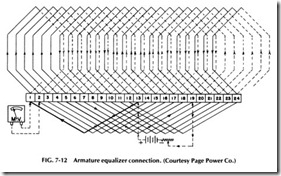
The principal purpose of equalizers is to connect together on the ar mature those points which have the same polarity and which should have equal potential. See Fig. 7-12. For a four-pole winding this means commu tator bars 180° apart; for a six-pole armature, bars 120° apart; and for an eight-pole machine, bars 90° apart. The number of bars spanned by the equalizer will equal bars divided by pairs of poles. For the armature shown in Fig. 7-12 each equalizer will span 24/2 or 12 bars, thereby mak ing the connection 1and 13, 2 and 14, etc. The pitch for any other number of bars or poles would be determined by the same method.
To test such an armature, current must be fed to the armature from an external low-voltage de supply, such as a battery, the leads being connected to commutator segments one half of the equalizer pitch apart.
Since the equalizer pitch is 12 segments in this case, the leads will be spaced six bars apart or 1and 7. Any pair of bars so spaced may be used in a fully equalized armature, bars 13 and 15 being employed in the diagram in Fig. 7-12.
The value of the test current is adjusted to give satisfactory deflection on the millivoltmeter, and the voltage drop readings are taken be tween all adjacent pairs of segments. These readings are interpreted in the usual manner, low readings indicating shorts and high readings showing high-resistance connections or opens. By tracing the winding and also by actual test, it will be noted that if the readings from bars 13 and 19 are forward, then the readings from 19 to 1 will be backward, 1 to 7 will be forward, and 1 to 13 backward. This is a normal indication obtained in all windings.
If the factors mentioned are kept in mind, the procedure given will produce consistently accurate results. It is to be noted such an armature will, when tested on a growler, give a shorted indication on all coils, even though the winding is in perfect condition. The reason for this can be seen by tracing from bar 1 through the coil to bar 2, through the equalizer to bar 14, through the coil to bar 13, and back through the equalizer to bar Thus every coil on the armature is apparently short-circuited by hav ing another coil placed in series with it through the equalizer connections. This explains the need for a special testing procedure.
WINDING SMALL ARMATURES
To understand how a small de motor armature is wound, a step-by-step description should prove helpful. A small two-pole, two-element, nonsym metrical armature having 12 slots and 24 segments will be used as an ex ample.
The slots should first be lined with fish paper about 7 to 10 mils thick and varnished cambric about 7 mils thick. The fish paper is placed in the slot first, next to the iron core, and the varnished cloth or cambric is placed inside the fish paper. To complete the insulation of the core, use a fiber lamination at each end, which is shaped the same as the iron core laminations and has the same number of slots stamped in it. This pro tects the coils at the corners of the slots.
The armature should be held or clamped with the commutator end next to the winder.
In winding the first coil, the number of turns will depend on the size of the armature and its voltage rating. If this number is taken from coils in an old winding, the turns in one or more of the old coils should be very carefully counted .
When winding an armature that has twice as many bars as slots, wind two coils in each slot, thereby providing enough coil leads for all bars.
The first coils for this armature will go in slots 1 and 7, winding to the right of the shaft, at both the front and back ends of the core. After winding in one coil, a loop about 4 in. long should be made at slot 1. Then continue and wind the same number of turns again, still in slots 1-7. When the last turn is finished, run the wire from the seventh slot over to the second and make a loop at slot 2. Next wind a coil in slots 2 and 8 and again make another loop at slot 2. Then place another coil in the same slots 2 and 8 and finish with a loop at slot 3, etc. This places two coils and two loops in each slot, and the same procedure should be followed until there are two coils and two loops in every slot.
The slot insulation should then be folded over the tops of the coils and the wedges driven in.
The loops are next connected to the commutator, one loop to each segment, and they should be connected in the same way they were made in the winding. That is, the first and last single wires are brought together and connected to a segment straight out from the first slot. The second loop in the first slot is connected to the next bar, and the first loop in the second slot is connected to the next, etc.
To avoid mistakes, these loops should be marked with cotton sleev ing which is slipped on over them as they are made. Red sleeving could be used on the first loop of each slot and white sleeving on the second, which will make it easy to locate the first and second loops for each slot. This winding would be used in a two-pole frame and has two circuits with 12 coils in each. If 120 V were applied to this winding, the voltage between adjacent commutator segments would be 120/12 or 10 V, which is not too high between adjacent bars. If this same armature had a commutator of only 12 segments, the voltage between bars would be 120/6 or 20 V, which is a little high for an armature of this size.
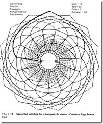
A typical lap winding for a two-pole de motor is shown in Fig. 7-13,
while various armature winding connections are shown in Fig. 7-14.


