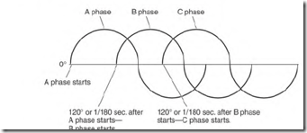
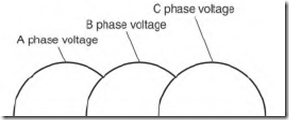
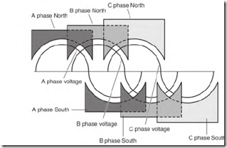
The operating characteristics of the three-phase induction motor are directly linked to the three-phase alternator that powers it. The positioning of the stator poles in both is identical. The voltage sine wave (Fig. 5.4) produced by the three-phase alternator is a picture of how the poles are connected in both the motor and the alternator.
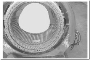
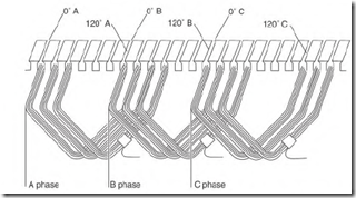
The alternator has three single-phase windings, spaced 120 0 apart in its stator (Fig. 5.5). Figure 5.6 shows the coils that form the first pole of phase A, phase B, and phase C. If a magnet is passed over the coils, the voltage generated in them produces a sine wave like the one shown in Fig. 5.7. The voltage produced is spaced 120 0 apart (like the coils). At 60 Hz, 120 0 in time equals 1/280 second. Voltage peaks in each of the three phases 1/280 second apart. Figure 5.8 shows the polarity of six three-phase poles and how they fit the sine wave.
FIGURE 5.4 The three-phase voltage sine wave. The shape of the sine wave makes it easy to compare with the poles of a stator.
FIGURE 5.5 The stator of a three-phase alternator has windings that are identical to a three-phase motor. Smith Services.
The Rotating Magnetic Field in a Three-Phase Motor
A three-phase motor has three single-phase windings. They are positioned 120 0 apart, identical to those of the three-phase alternator previously described. The following is a simplified version of the three-phase rotating magnetic field.
FIGURE 5.6 One pole from each of the three phases. (Poles are separated120 electrical degrees from each other.)
FIGURE 5.7 Voltage sine wave created by the three poles (if a magnet is passed over them).
FIGURE 5.8 Windings of a two-pole stator are connected to fit the sine wave.
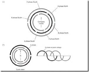
Figure 5.9a is a two-pole stator with a compass needle centered in it.
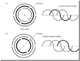
When DC is applied to phase A, the compass needle will align as shown in Fig. 5.9b. Applying DC to phase B moves the compass needle 120 0 , aligning it with phase B (Fig. 5.9c). And DC applied to phase C moves the compass needle another 120 0 , aligning it with phase C (Fig. 5.9d).
Applying DC as shown in Fig. 5.9 creates a rotating magnetic field (like three-phase power). Rotation is produced when three voltages (spaced 120 ![]() in time) are applied to three phase windings (spaced 120 0 from each other). Alternate phases will reach peak magnetism at 1/280-second intervals.
in time) are applied to three phase windings (spaced 120 0 from each other). Alternate phases will reach peak magnetism at 1/280-second intervals.
FIGURE 5.9 (a) Two-pole stator showing a north pole and a south pole for each phase. (b) When DC is applied to the A phase, the compass aligns itself as shown.
FIGURE 5.9 (c) The compass needle moves 120 degrees when DC is applied to the B phase. (d) When DC is applied to the C phase, the compass needle moves another 120 degrees.
resulting in a rotating magnetic field. The moving magnetic lines of force cut the bars of the rotor’s squirrel cage winding, creating poles in the rotor iron.
Single-Phase Condition
A three-phase motor won’t start with one of its lines open. When one line is open, single-phase is applied to two of the motor’s three windings and one winding is inactive. of the three single-phase windings (spaced 120 ![]() apart) are energized. Current in the two windings is in unison. Magnetism of both windings peaks at the same time, as though they were one winding. There’s no rotating magnetic field. Since the rotor pole magnetism has no stator pole magnetism to react to, there is no torque. A pulsing, high current will flow in the rotor and the stator windings.
apart) are energized. Current in the two windings is in unison. Magnetism of both windings peaks at the same time, as though they were one winding. There’s no rotating magnetic field. Since the rotor pole magnetism has no stator pole magnetism to react to, there is no torque. A pulsing, high current will flow in the rotor and the stator windings.
If the shaft is spun fast enough, the motor will run as a single-phase motor. The motor’s power, however, drops to slightly more than one-half
its nameplate value. If a fully loaded motor is running when single phasing occurs, the energized part of its winding overheats and chars. This is explained and illustrated in Chapter 6, Fig. 6.35.
