Objectives
After studying this unit, the student will be able to:
• Develop a wiring diagram using this schematic
• Connect this circuit
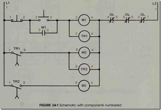
The circuit shown in figure 34-1 is the same as the schematic shown in figure 31-1, except the schematic in 34-1 has been labeled with numbers. Figure 34-2 shows the components of the wiring
diagram. The numbers used to label the compo nents in the wiring diagram correspond to the numbers in the schematic. For instance, the sche matic shows the numbers 1 and 8 beside normally
open contact TRI. The wiring diagram also shows the numbers 1 and 8 beside normally open contact TRI. The numbers used with each component shown on the schematic have been placed beside the proper component shown in the wiring diagram.
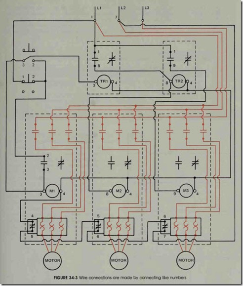
Figure 34-3 shows the wiring diagram with connected wires. Notice that the wiring diagram shows motor connections while the schematic does not. Although it is a common practice to omit mo tor connections in control schematics, wiring dia grams do show the motor connections.
Review Question
1. Referring to circuit 34-1, would it be possible to change the components that have been numbered with an 8 to a number 9, and the components that have been numbered with a 9 to a number 8 without affecting the operation of the circuit?


