Control Components
As soon as it has been decided what functions of control are needed for a machine, the components or devices to perform these functions must be selected. This selection should be made with care. For instance, if a float switch is needed and its duty cycle is only a few operations per day for a year or so, one of the cheaper competitive units might be satisfactory. If, how ever, the duty cycle is a few hundred operations per day on a permanent basis, then the best-quality unit available should be used. The small savings gained through the use of cheap components are usually soon offset by costly shutdowns due to failure of the components to function properly. In this chapter each of the basic types of control components will be discussed, how it works, both electrically and mechanically , and at least some of the functions that it can perform.
The student is strongly urged to obtain manufacturers’ catalogs on control components as a further reference for use with this chapter. The more familiar the student becomes with the various manufacturers’ equipment and the way it operates, the better prepared he will be to service it on the job.
3 ·1 SWITCHES AND BREAKERS
The one component common to all but the very smallest motors is a switch or breaker for disconnecting the motor. There are two types of switches in general use on motor circuits. The first of these is the isolation switch, which is rated only in voltage and amperage. This type of switch has no interruption-capacity rating and must not be opened under load. Quite often the switch used for this purpose is a nonfused type. Such switches are per mitted by the national electrical code only for motors of 2 hp or less and over 100 hp.
The second type of switch is a motor-circuit switch, which is capable of interrupting the motor current under normal over loads. This type of switch is rated in horsepower and, when used within this rating, is capable of being used as a start ing switch for motors (Sec. 2 ·1). When used for disconnecting and motor-circuit protection, this switch must be of the fused type.
Circuit breakers offer the same disconnecting features as switches and the circuit protection of fuses. The breaker operates on a thermal-released latch so that it may be reset and used again after an overload. Being built all in one unit and offering short-circuit protection, as well as serving for disconnecting , makes this unit more compact than a switch and fuse combina tion. Switches do offer more visual indication that the circuit is open.
Switches and breakers may perform the functions of start (Sec. 2 ·1), stop (Sec. 2 ·16), overload protection (Sec. 2 ·7) , and short-circuit protection (Sec. 2 ·8), depending upon their rating and use in the circuit.
3 ·2 CONTACTORS
The contactor itself is not generally found alone in motor-control circuits. lt is, however, the basic unit upon which the motor starter is built. Contactors are used to perform the functions of start and stop on many heavy loads such as electric f urnaces, signs, and similar types of equipment that do not require running protection.
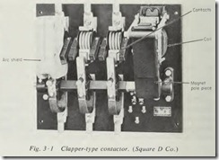
Perhaps the best way to describe a contactor would be to say that it is a magnetically closed switch. It consists of one set of stationary contacts and one set of movable contacts which are brought together by means of the pull of an electromagnet. The vast majority of contactors use an electromagnet and con tact arrangement that falls into one of two general types. The first of these is the clapper type (Fig. 3 ·1). The contacts are fastened to the pole pieces of the magnet and hinged so that they swing more or less horizontally to meet the stationary contacts.
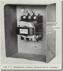
The second is the solenoid type (Fig. 3 ·2). On this contactor the movable contacts are coupled to the movable core of a magnet. When the electromagnet is energized , the movable core is pulled to the stationary core, thus closing the contacts.
Regardless of whether the contactor is of the clapper or the solenoid type, the contacts themselves are broken by the pull of gravity or the force of a spring when the electromagnet is deenergized.
All that is necessary electrically to operate the contactor is to provide a voltage of the proper value to the coil of the electro magnet. When the voltage is switched on, the contacts close, and when the voltage is switched off, the contacts open.
3·3 RELAYS
Automatic control circuits almost invariably contain one or more rel ays, prim arily because the relay lends flexibility to our control circuits. The relay is by design an electromechanical amplifier.
Let us consider for a moment the meaning of the word am p lify. It means to enlarge, increase, expand, or extend. When we energize the coil of a relay with 24 volts and the contacts are controlling a circuit of 460 volts, we are amplifying the voltage through the use of a relay. Relay coils require only a very low current in their operation and are used to control cir cuits of large currents. So again they amplify the current. The relay is inherently a single-input device in that it requires only a single voltage or current to activate its coil. Through the use of multiple contacts, however, the relay can be a multiple-output device which amplifies the number of operations controlled by the single input.
Suppose we have a relay whose coil operates on 115 volts at 1 amp, and the contacts of this relay control three separate circuits operating at 460 volts and 15 amp each. This relay then becomes a power amplifier in that it controls considerably more power in its output circuits than it consumes in its input circuit. It also becomes an amplifier in terms of the number of circuits, as its single input controls three separate outputs.
Relays are generally used to accept information from some form of sensing device and convert it into the proper power level, number of varied circuits, or other amplification factor which will achieve the desired result in the control circuit. These sensing devices used in conjunction with relays are commonly called pilot devices and are designed to sense or detect such things as current, voltage, overload, frequency, and many others, including temperature. The proper type of relay to be used in a given circuit will be determined by the type of sensing device which transmits the information to it. For instance, a voltage sensing device must be connected to a voltage relay, and a cur rent-sensing device must activate a current relay. Each of these types will be discussed individually.
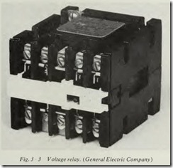
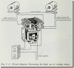
Voltage Relay. This type of relay (Fig. 3 ·3) is probably the most common because it lends itself to so many applications and can be used to perform so many functions. The voltage relay is merely a small contactor (Sec. 3 ·2) which opens or closes its contacts, depending on whether they are normally closed or open whenever the proper voltage is applied to its coil. They are available with as many contacts either normally open or normally closed as needed. Voltage relays are used frequently to isolate two or more circuits controlled from one source (Fig. 3 ·4) or when the control voltage is different from line voltage.
It must be remembered that while a voltage relay is not a primary control device, it does require a pilot device (Chap.4) to operate it.
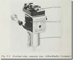
Current Relay. This type of relay (Figs. 3·7, 3·8, and 3·9) is used to open or close a circuit or circuits in response to current changes in another circuit, such as a current drawn by a motor (Sec. 2 ·1).
The current relay is designed so that when connected in serieswith the circuit to be sensed, it will close after the current through its coil reaches a high enough value to produce the necessary magnetic flux. There are a few terms used in connec tion with current relays that must be understood .
Pull-in current is the amount of current through the relay coil necessary to close or pull in the relay.
Drop-out current is the value of current below which the relay will no longer remain closed after having been pulled in.
Differential is the difference in value of the pull-in and drop out currents for the relay in question.
For example, if a relay is energized or pulled in at 5 amp and drops out at 3 amp, then the pull-in current is 5 amp, the drop-out current is 3 amp, and the differential is 2 amp.
Most relays of this type are provided with spring tension and contact spacing adjustments which allow a reasonable variation of pull-in, drop-out, and differential values. This type of relay should not be operated too close to its pull-in or drop-out values unless it is provided with some form of positive throw device for its contacts. This is important because the amount of contact pressure depends upon the difference in actual current and pull in current for the particular relay. For example, when the above relay is operated with only 5.01 amp flowing through the coil, the contact pressure will be only that produced by the 0.01 amp of current.
Generally, true current relays are used only on circuits of very low current. For heavier current applications, a current transformer is used and its output applied to either a current relay or a voltage relay with the proper coil voltage.
Another type of current relay is the thermal type, in which a bimetallic strip or other device is heated by a coil connected in series with the circuit to be sensed . The bimetallic type de pends upon the difference in expansion of two dissimilar metals when heated. It is·constructed by riveting together two thin strips of dissimilar metals. When the current in the circuit produces sufficient heat, the bimetallic strip expands and releases the con tacts. Motor overload relays and fluorescent starters are exam ples of this type of relay.
Frequency Relay. The frequency relay is used to apply field excitation to synchronous motors (Sec. 2 ·5) and for acceleration control on wound-rotor motors. Most of these units are specially designed for a particular application. One type consists of two balanced coils arranged on a common armature. These coils compare a reference frequency with that of the sensed circuit. The relay is closed one way when the frequencies are the same, or within a predetermined percentage, and is closed the other way when the frequencies differ by a given amount or more.
Time-delay Relay. This type of relay is often used for sequence control, low-voltage release, acceleration control, and many other functions.
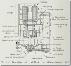
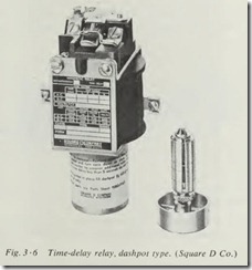
Essentially, the time-delay relay is the voltage relay with the addition of an air bleed (Fig. 3 ·5) or a dashpot (Fig. 3 ·6) to slow down or delay the action of its contacts. This delay in action can be applied when the relay is energized or when it is deenergized.
If the delay is to be applied when the relay is energized, it is referred to as on DELAY (TDOE). If the delay is to be applied when the relay is deenergized, then it is referred to as off DELAY (TDODE). Both types are provided with an adjustment so that the time delay can be set within the limits of the particular relay. The contacts are always shown in the deenergized positionand are either time opening (TO) or time closing ( TC). These units are built in various sizes depending upon the contact rating needed.
Overload Relay. The overload relay is found on all motor starters in one form or another. In fact the addition of some form of overload protection to an ordinary contactor converts it into a motor starter. This unit performs the functions of over load protection (Sec. 2 ·7) and phase-failure protection (Sec. 2 ·13) in motor circuits. The basic requirement for overload protection is that the motor be allowed to carry its full rated load and yet prevent any prolonged or serious overload. When a motor is overloaded mechanically, motor current increases, which in turn increases the temperature of the motor and its windings. The same increases in current and temperature are caused by the loss of one phase on polyphase motors or a partial fault in the motor windings. Therefore , to give full overload protection we need only to sense, or measure, the current drawn by the motor and break the circuit if this current exceeds the rated value for the motor.
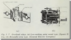
There are three basic types of overload relays in general use on across-the-line starters. The first is a unit which employs a low-melting-point metal to hold a ratchet (Fig. 3 ·7a), which when released causes the opening of a set of contacts in the coil circuit of the starter. The second type uses a bimetallic strip ( Fig. 3 ·7b) to release the trip mechanism and open the coil-circuit contacts.
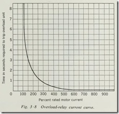
Regardless of which type of device is used, it is activated by a heating element placed in series with the motor circuit. The amount of current needed to cause the relay to trip is deter mined by the size of the heating element used. When used for protection of small motors drawing low current, a coil of small wire or very thin metal is used as a heating element. On larger motors a heavier coil or strip of metal is used so that the same amount of heat is produced when the rated amount of current flows. Thermal units used in overload relays have an inherent time delay in their action that is inversely proportional to the amount of overload. This should be evident from a study of the curve shown in Fig. 3 ·8. When the overload is slight, the motor can go on running for some time without tripping the overload unit. If the overload is great, however, the overload relay will trip almost at once, thus removing the power from the motor and preventing damage.
Thermal relays trip on heat and heat alone, and they cannot normally tell whether this heat is from the current to the motor or from the air that surrounds the starter. To offset this, it is sometimes necessary to install oversized heaters in high-tempera ture locations and undersized heaters in low-temperature loca tions. Some bimetallic units are designed to compensate for the ambient temperature change. This type of unit is called a com pensated overload relay.
The third type of overload relay is magnetic (Fig. 3 ·9). This unit has a magnetic coil so connected that it senses the motor current either by the use of current transformers or by direct connection. When the current exceeds the rating of the motor, the overload coil lifts a plunger that forms its core and opens the contacts in the control circuit. Magnetic overload relays are generally found only on large motor starters.
Overload relays must be reset after each tripping , either auto matically or manually. The automatic reset type should not be used except on equipment that is so designed, or used, that there can be no danger to life or equipment from the restarting of the motor. After the overload relay has been tripped, it requires a little time to cool, so that there is some delay before resetting can be accomplished.
3·4 MOTOR STARTERS
A motor starter in its simplest form consists of some means of connecting and disconnecting the motor leads from the line leads, plus overload protection for the motor. Many other refine ments are added to this basic unit to achieve the desired degree of control and protection. There are many types and classifica tions of motor starters. Each of these types draws its name from the method or classification of operation of the motor that it starts. Some of these classifications are manual or automatic, full-voltage, or reduced-voltage, single-phase or three-phase, and d-e or a-c. To describe a particular motor starter, it is necessary to use several of these terms or classifications. For instance, a particular motor might require a reduced-voltage, automatic, three-phase, a-c motor starter. Even this does not completely describe the unit, because it must be of a definite size for the motor and be rated for the proper voltage. Then we must know whether it is to be remotely controlled or to have a push button in the cover and many other features. In this chapter, we shall discuss many of these classifications, and the student should keep in mind that any particular starter might well be a combination of several of the types we discuss here.
Keep in mind that there is a difference between a motor starter and a motor controller. While it is difficult to draw a fine line between them, for the purpose of the discussion in this book the starter consists of the means of connecting the motor to the line plus providing the protection needed. By contrast, a controller contains not only the motor starter but at least a major part of the sensing devices and relays necessary for the complete control system.
Motor starters are built to NEMA (National Electrical Manu facturers Association) standards. These standards include such things as sizes, so that a purchaser may expect the equipment to be built to handle its rated load. For instance, the size 0 starter in 460-volt three-phase service is rated at 5 hp. At 660 volts the size one starter is rated at 10 hp, size two 25 hp, size three 50 hp, and size four 100 hp. For lower voltage service, each size starter has a smaller horsepower rating because of the in creased current demand by the motor running at a lower voltage.
Also included in the NEMA standards are types of enclosures for starters to satisfy code requirements for atmospheric condi tions existing in the place of installation . NEMA type 1 enclo sures are for general purpose indoor use wherever atmospheric conditions are normal. They are intended primarily to prevent accidental contact with the control apparatus and energized circuits. NEMA type 3 enclosures are weather-resistant and pro tect against dust, rain, and sleet in outdoor applications. NEMA type 4 enclosures are watertight and suitable for outdoor appli cations on piers and in dairies and breweries. They may be washed down with a hose. NEMA type 7 enclosures are intended for use in hazardous gas locations such as are found in oil fields and satisfy the code requirements for class 1, group D, locations. NEMA type 8 enclosures are also intended for hazardous gas locations and have oil-immersed contacts. NEMA type 9 en closures are built for use in hazardous dust locations, whose code classification is class 2, groups E, F, or G, such as flour mills. NEMA type 11 enclosures are corrosion-resistant enclosures that protect the enclosed equipment against corrosive effects of gases and fumes by immersing the equipment in oil. NEMA type 12 enclosures are dust-tight industrial enclosures and are designed for use where the enclosure is required to provide protection against dirt and oil.
If you were requested to order the starter for a 5-hp motor connected to a 230-volt three-phase line in ordinary service, you would need to specify several things. You would order a size 1 three phase 230-volt across-the-line starter in a NEMA type 1 enclosure. Additional information would be needed as to whether the starter should be manual or automatic, depending upon the type of control to be utilized in the installation.
3·5 MANUAL MOTOR STARTERS
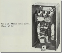
To be classed as manual, a motor starter must depend upon the operator closing the line contacts by pushing a button or moving a lever which is physically linked to the contacts in some manner. For an illustration, suppose we take the size 0 starter available in either manual or automatic type, having the push button in the cover. The manual type (Fig. 3 ·10) is so constructed that when the START button is pressed, a mechanical linkage forces the contacts to close. Once closed, the linkage is latched in this position. When the STOP button is pressed, or the overload units open, the linkage is tripped and the con tacts open.
By contrast, when the START button is pressed on the magnetic starter, it merely energizes the starter coil, which in turn mag netically closes the line contacts. The STOP button or the over load relays break the circuit to the coil, thus allowing the line contacts to open.
The chief disadvantage of the manual starter is the utter lack of flexibility of control. It must be operated from the starter location, and it is definitely limited even as to protection-control possibilities. When the degree of control it offers is satisfactory for the installation, it does have the advantage of being less expensive. The vast majority of manual starters found in service will fall into one of three classes, namely, the thermal switch for use on very small single-phase motors, the size 0 and size 1 manual across-the-line starters in single- and three-phase motors, and the manual reduced-voltage compensator (Fig. 3 ·14) for large motors.
