2 ·10 INTERLOCKING PROTECTION
Interlocking is preventing one motor from running until some other motor or sequence has been activated. A good example of this is found in air conditioning. If the compressor were to run without the cooling-tower pump running, the compressor head pressure would rise dangerously, and either the high-limit pressure switch would shut the machine down or the compressor would be damaged. To prevent this from occurring, the compressor should be interlocked to the pump so that it cannot start until the pump is running.
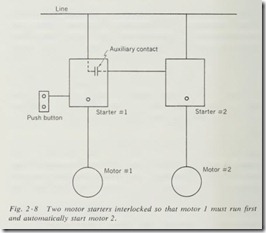
Interlocking may be electrical or mechanical or a combination of both. Reversing starters built with both starters in the same box generally have a mechanical interlock and sometimes have an electrical interlock. When the two units to be interlocked are in two separate boxes (Fig. 2 ·8), electrical interlocking is a necessity. Electrical interlocking is accomplished by connecting an auxiliary contact on one starter in series with the coil circuit of the second starter.
While we have discussed interlocking only in relation to motors, it is well to realize that interlocking is used in all phases of control wiring whether it is involved in the starting of a motor or in the closing of valves in a process-control installation. The use of interlocking control assures the proper sequence of opera tion for the entire control system
2 ·11 SPEED CONTROL
Squirrel-cage motors do not lend themselves to any system of continually variable speed control, but rather may be had in two, three, or four speeds according to the design of the motor. These were discussed under acceleration control. The most ver satile a-c motor as far as speed control is concerned is the wound-rotor motor, sometimes referred to as a slip-ring motor. By the use of secondary control , this type of motor can have as many steps of speed as are desirable. Methods of controlling wound-rotor motors will be discussed more fully when we take up their controllers.
Another type of a-c motor which gives excellent speed control is the a-c commutator type of motor.
There are four general types of speed control, depending on the requirements of the machine:
Constant Speed Control. Many machines require only a reduced speed for starting and then a constant speed for operation. This type of speed control may be accomplished by using a reduced-voltage starter on either a squirrel-cage , wound-rotor , or synchronous motor. It must be kept in mind , however, that reduced-voltage starting also invariably gives reduced starting torque.
Variable Speed Control. Variable speed is a requirement that a motor must operate at several different speeds at the selection of the operator. This type of control may best be accomplished by the use of a wound-rotor motor with a secondary controller or a commutator-type a-c motor. This type of control requires that a speed change be made under load.
Multispeed Control. This type of control differs only slightly from variable-speed control in that it usually does not require speed changes under load. The multispeed squirrel-cage motor is well suited for this type of service.
Predetermined Speed Control. With this type of control, the machine is accelerated through the necessary steps of speed to a preset operating speed. Both multispeed squirrel-cage and wound-rotor motors are suitable for this type of service.
Any of the above types of speed control may be wired so that the operator may vary the sequence of operation. Quite frequently, however, the control system compels the operator to start at a particular place in the sequence and follow it through without variation. When the control is of his type, it is known as compelling sequence control. This term also applies to control systems other than speed control and is dependent only on the requirement that it compels the operator to follow a set sequence of operation.
2 ·12 UNDERVOLTAGE PROTECTION AND RELEASE
The line voltage supplying motor circuits may drop to danger ously low values or may be shut off at almost any time. When the voltage is too low, severe damage may be done to the motor windings if they are allowed to remain on the line. While some large motors employ a special voltage relay to disconnect the motor under low-voltage conditions, most smaller motors depend on the overload units to open the starter contacts.
If the control circuit is such that the motor will restart when the power is restored to its proper value, the protection is re ferred to as undervoltage release. The use of maintained-contact pilot devices on magnetic starters gives this type of protection.
If the protection used requires that the motor be restarted manually, then the protection is referred to as undervoltage pro tection. The use of momentary-contact pilot devices on magnetic starters gives this type of protection.
Whether to use undervoltage protection or undervoltage release depends upon the requirements of the machine. Ventilating fans, unit heaters, and many other small units in a plant may operate more effectively with undervoltage release. This saves the necessity of having to restart them. In any machine where there is the slightest risk that the machine or operator might be injured by an unexpected start, undervoltagc protection should by all means be used.
2 ·13 PHASE-FAILURE PROTECTION
When a three-phase motor has the current interrupted on one phase , the condition is referred to as single phasing. Ordinarily the overload units will trip the starter and remove the motor from the line. There is, however, a condition of loading for each motor where it may quite possibly burn up without causing excessive current to flow through the overload units. This is generally about 65 percent of load for most squirrel-cage motors. For small motors the risk is generally considered too slight to warrant the cost of additional protection. For large motors a voltage relay is placed across each phase, and its contacts are connected in series with the holding coil of the starter. Failure of one phase will drop the starter out at once.
The use of three overload relay units on the starter gives what is generally considered adequate phase-failure protection for most motor installations up to 200 hp. Three overload relay units are now required by the national electrical code.
2 ·14 REVERSE-PHASE PROTECTION
Some machines could be severely damaged when the motor runs in reverse, as would occur with a reversal of phasing. While this is not a common type of protection, when it is needed it can prevent costly damage.
Reverse-phase protection can be accomplished by the use of a phase-sensitive relay with its contacts in series with the holding coil of the starter.
2 ·15 INCOMPLETE SEQUENCE PROTECTION
When reduced-voltage starting is used on a motor, there is a danger that the motor windings or the autotransformer or both might be damaged through prolonged operation at reduced volt age. To prevent this condition and to assure the completion of the starting cycle, a thermal relay is placed across the line during starting. This relay is so designed and connected that prolonged starting will cause the thermal unit on the relay to open its contacts and drop out the starter. This type of protection is also necessary on synchronous motor controllers .
Another method of obtaining incomplete sequence protection for starting of motors is by the use of the timing relay which will disconnect the motor if it has not completed its starting
sequence in the predetermined length of time.
2 ·16 STOPPING THE MOTOR
There are several factors that must be considered in stopping a motor. On some machines all that is necessary is to break the motor leads and let the motor coast to rest. Not all machines can be allowed to coast, however. For instance, a crane or hoist not only must stop quickly, but also must hold heavy loads. Other machines, such as thread grinders, must stop very abruptly, but need not hold a load.
The method of stopping may be either manual or automatic. Automatic stopping is accomplished by the use of limit switches, float switches, or other automatic pilot devices. Manual stopping is controlled by push buttons, switches, or other manually op erated pilot devices.
The most common method of stopping is merely to remove the motor from the line by breaking the circuit to the starter coil, if it is a magnetic starter, or by tripping the contacts of a manual starter with the STOP button.
For motors that must be stopped very quickly and accurately but which do not need to hold a load, probably the most widely used method is known as the plugging stop. This is accomplished by the use of an automatic plugging switch or a plugging push button in conjunction with a reversing starter.
With either of these units, the motor starter is dropped out and then momentarily energized in the reverse direction. The momentary reversal plugs the motor to an abrupt stop. This type of stopping will not do for cranes or hoists because it will not hold a load.
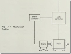
When dealing with equipment such as cranes and hoists, we must consider that the load has a tendency to turn the motor. This is known as an overhauling load. When a-c motors are used, they frequently are of the wound-rotor type and stopping is preceded by a slowing of the motor through one or more steps. This slowing helps to nullify the overhauling load. As the motor is dropped from the line, a mechanical brake (Fig. 2 ·9) is automatically applied which locks the motor shaft con nected to the load .
When d-e motors are used, the overhauling load is slowed down by the use of dynamic (regenerative) braking; then a friction brake is applied.
Synchronous motors are sometimes stopped by the use of dynamic braking. This is accomplished by removing the line from the motor while placing a resistance across the motor leads, thus making an a-c generator out of the motor. The resistor presents a heavy load to the generator, causing it to come to a rapid stop. Care must be taken to use a resistor unit capable of dissipat ing the power generated while stopping the motor. It must also be noted that this type of stop cannot be used for frequent stop ping because the resistor units must have time to cool between operations.
2 ·17 STARTING D-C MOTORS
Any device used to start a d-e motor over about 1/4 hp must pro vide some means of limiting the starting current to approximately 150 percent of full-load value. An a-c motor offers a high impedance to the line which will limit the starting current. The d-e motor offers only the low resistance of the armature to limit inrush current until the motor begins to rotate.
Once rotation is started, the armature winding begins to cut the flux produced by the field, and a voltage is generated in the armature coil. The volta ge generated in the armature coil is opposite in polarity to the applied voltage and is referred to as counter electromotive for ce (cern!). The value of the counter emf increases with speed, until at full speed it is 80 to 95 percent of the applied voltage.
Armature current is calcula ted by subtracting the counter emffrom the applied voltage and dividing by the armature resistance. When the armature is at rest, the counter emf is at zero. There fore, the armature current is equal to the applied voltage divided by the armature resistance, which is very low, generally 1 to 2 ohms or less.
If we assume an armature resistance of 0.85 ohm and anapplied voltage of 110 volts, the initial inrush current would be 129.4 amp. At full speed the counter emf would be about 100 volts and would limit the current to 11.8 amp. The starting cur rent should be limited to about 150 percent of full-load current by connecting a resistor of 650 ohms in series with the armature.
The series resistance must be removed in steps as the accelera tion of the motor produces an ever-increasing counter emf and reduces the resistance required, until at rated speed all resistance is removed. A d-e motor develops its greatest power when the counter emf is at its maximum value.
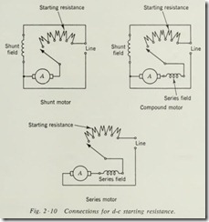
When series or compound motors are used, the starting resistance is connected in series with the armature and series field. The shunt motor has no series field, and therefore the resistance is connected in series with the armature only ( Fig. 2 ·10).
2 · 18 SPEED CONTROL OF D-C MOTORS
D-e motors are used chiefly because of their speed-co ntrol char acteristics, which make them the best suited for many drive requirements.
When a d-e motor has its rated armature voltage and rated field voltage applied, it runs at its base speed. Speeds below base speed ( underspeed) are achieved by maintaining the field voltage at rated value and reducing the armature voltage. Speeds above base speed (overspeed) are achieved by maintaining the armature voltage at rated value and reducing the field voltage .
The series motor’s speed is controlled by the amount of resis tance conn ted in series with the armature and series field. The resistors used for speed control must be rated for continuous duty rather than starting duty, since they are in the circuit when ever the motor is used at less than base speed.
The most common controller for speed control of senes motors is the drum controller used with heavy-duty resistance grids.
Shunt and compound motors lend themselves well to applica tions where speed control is a major consideration. When the speed desired is over the base speed (overspeed control), resis tance is added in series with the shunt field. When the speed desired is below the base speed (underspeed control), resistance is added in series with the armature.
The most popular manual controller for speed control of shunt and compound motors is the combination four-point starter and speed controller ( Sec. 3 ·14) .
Summary
A student beginning the study of motor control may feel that he will never learn all the functions that might be performed in the control of a motor or other device, and well he might. The advances made in this field are so rapid and far-reaching that new ones are developed almost daily. When analyzed com pletely, however, most of them are merely variations of the basic functions set forth in this chapter. It must be kept in mind that intelligent servicing, development, or installation of control equipment depends upon a thorough understanding of the re quirements of the machine and the characteristics of the motor.
Review Questions
1. What is motor control?
2. What are the three ba sic types of motor control?
3. Name the two types of starting control.
4. How many types of protection are there for motors?
5. Do the running conditions of the motor affect the type of control to be used on a motor?
6. What is the difference between an automatic and a semiautomatic controller?
7. What factors need to be considered when selecting starting equipment?
8. What are the two basic methods of reduced-voltage starting?
9. How can the acceleration of motors be controlled automatically?
10. Reversing starters must be equipped with some form of to prevent both starters from closing at the same time.
11. When the motor is momentarily reversed to bring it to a stop,the function is called .
12. Is the time it takes the overload relay to drop out the starter affected by the percentage of overload?
13. What is the difference between overload and short-circuit protection?
14. What is incomplete sequence protection, and on what two types of motors would it most likely be used?


