Plugging
Plugging is defined by NEMA as a system of braking in which the motor connections are reversed so that the motor develops a counter torque that acts as a retarding force. Plugging can be used with direct current mo- tors but is more often used with three-phase squirrel cage motors. Plugging is accomplished with three- phase motors by disconnecting the motor from the power line and momentarily reversing the direction of rotation. As a generally rule, the reversing contactor is of a larger size than the forward contactor because of the increased plugging current. There are several methods that can be employed when a plugging control is desired.
Manual Plugging
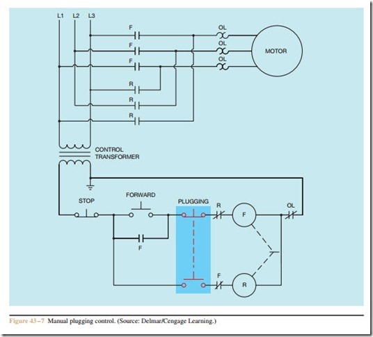
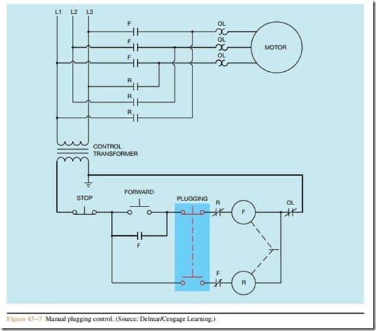
One type of plugging control depends on an opera- tor to manually perform the operation. A manual plugging control is shown in Figure 43 – 7. The circuit is basically a forward-reverse control circuit, with the exception that there is no holding contact for the reverse contactor. Also, the PLUGGING push button is a double acting push button with the normally closed section connected in series with the forward contactor. This permits the PLUGGING push button to be used with- out having to press the STOP button first.
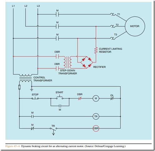
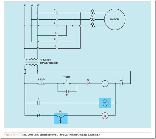
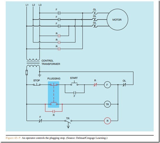
One method of providing plugging control is with the use of an automatic timed circuit (Figure 43 – 8). This is the same basic control circuit used for time con- trolling a dynamic braking circuit in Figure 43 – 6. The dynamic brake relay has been replaced with a reversing contactor. A modification of this circuit is shown in Figure 43 – 9. This circuit permits an operator to select if a plugging stop is to be used or not. Once the opera- tor has pressed the PLUGGING push button, the timer controls the amount of plugging time.
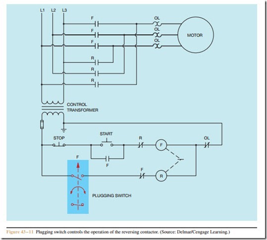
Although time is used to control plugging, problems can occur due to the length of plugging time. If the timer is not set for a long enough time, the reversing circuit will open before the motor completely stops. If the timer is set
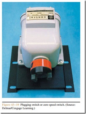
too long, the motor will reverse direction before the re- versing contactor opens. The most accurate method of plug stopping a motor is with a plugging switch or zero speed switch (Figure 43 – 10). The plugging switch is connected to the motor shaft or the shaft of the drive ma- chine. The motion of the rotating shaft is transmitted to the plugging switch either by a centrifugal mechanism or by an eddy current induction disc inside the switch. The plugging switch contact is connected to the coil of the reversing starter (Figure 43 – 11). When the motor is started, the forward motion of the motor causes the normally open plugging switch contact to close. When the STOP button is pressed, the normally closed F contact connected in series with the reversing contactor will re-close and reverse the direction of rotation of the motor. When the shaft of the motor stops rotating, the plugging switch contact will reopen and disconnect the re- versing contactor.
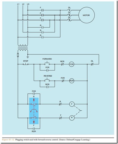
Plugging switches with two normally open contacts can be obtained for use with forward-reverse controls. These switches permit a plugging stop in either direction when the STOP button is pressed (Figure 43 – 12). The direction of motor rotation will deter- mine which switch closes. The switch symbol indicates the direction of rotation necessary to cause the switch contacts to close.
Review Questions
1. Name three methods of braking a motor.
2. How is the braking force of drum type brakes controlled?
3. Why are mechanical brakes often used on cranes?
4. What is the advantage of dynamic brakes over mechanical brakes?
5. What is the disadvantage of dynamic brakes when compared to mechanical brakes?
6. The amount of counter torque developed by a direct current generator is proportional to what?
7. When using dynamic braking for a direct current motor, how is the braking time controlled?
8. Name three factors that determine the amount of induced voltage.
9. How is dynamic braking for direct current motors accomplished?
10. How is the dynamic braking force of an alternat- ing current motor controlled?
11. How is a plugging stop accomplished?
12. What device is generally used to accurately stop a motor when a plugging stop is used?
13. Refer to the circuit shown in Figure 43 – 11. When the START button is pushed and the motor starts in the forward direction, the plugging switch will close. What prevents the reversing contactor from energizing when the plugging switch contact closes?
