Three-phase inverter
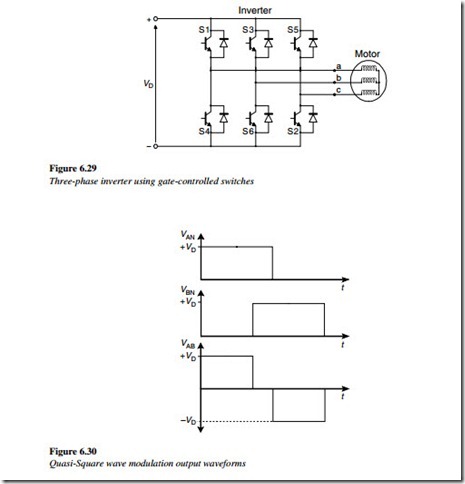
A three-phase inverter could be constructed from three inverters of the type shown earlier. However, it is more economical to use a six-pulse (three-leg) bridge inverter as shown in Figure 6.29.
In its simple form, a square output voltage waveform can be obtained by switching each leg high for one half-period and low for the next half-period, at the same time ensuring that each phase is shifted one third of a period (120º), as shown in the Figure 6.30.
The resulting phase-to-phase voltage waveform comprises a series of square pulses whose widths are two-thirds of the period of the switch, in each phase.
The resulting voltage waveform is called a quasi-square wave (QSW) voltage. This simple technique was used in early voltage source inverters (VSI), which used the forced commutated thyristors in the inverter bridge. To maintain a constant V/f ratio, the rectifier bridge controlled the magnitude of the DC bus voltage, in order to keep a fixed ratio to the output frequency, which was controlled by the inverter bridge. This technique was also known as the pulse amplitude modulation (PAM).
The output voltage of a three-phase converter has a harmonic spectrum, very similar to the single-phase square wave, except that the triplen harmonics (harmonics whose frequency is a multiple of three times the fundamental frequency) have been eliminated. In an inverter with a three-phase output, this means that the 3rd, 9th, 15th, 21st, etc. harmonics are eliminated. To develop a three-phase variable voltage AC output of a particular frequency, the voltages VAN, VBN, VCN on the three output terminals a, b, and c in Figure 6.29 can be modulated on and off to control both the voltage and the frequency.
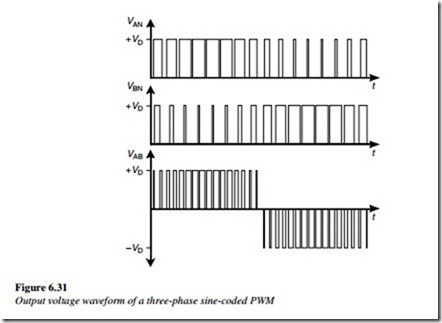
The pulse–width ratio over the period can be changed according to a sine-coded PWM algorithm (Figure 6.31).
When the phase–phase voltage VAB is formed, the present modulation strategy gives only positive pulses for a half period followed by negative pulses for a half period, a condition known as consistent pulse polarity. It can be shown that the consistent pulse polarity guarantees the lowest harmonic distortion, with most of the distortion being at twice the inverter chopping frequency. Therefore, these are the types of inverters used in industrial applications. The same methods are also used in AC drives.

