STEREO MULTIPLEXING
An FM stereo signal consists of two different audio frequency signals that occupy the same f.m. signal. The individual audio signals are identified as “left” (L) and “right” (R). In conventional programming, this pair of audio signals originated from a pair of microphones at a sound studio. The audio signal from the L microphone differs from that of the R microphone. Therefore, the stereo signal consists of two audio waveforms that vary independently in frequency and amplitude.
In monophonic FM transmission, a swing of + 75 kHz represents cent per cent modulation and produces sidebands that occupy the entire channel.
If high fidelity were not required, an FM channel could be divided into two equal parts for transmission of the L and R signals on individual carriers.
To transmit both the L and R signals with high fidelity in a single channel requires multiplex transmission. This is a technique that permits satisfactory separation of the L and R signals at the receiver. Two microphones are employed as the equivalent of a single microphone. When the L and R signals are mixed, the mono (L + R) signal is produced.
STEREO MULTIPLEX OBJECTIVES
Stereo multiplex is the system whereby the left-and- right-channel signals of a stereo program are both sent out on one f.m. broadcast channel. In the method standardised by the Federal Communications Commission (FCC), the following objectives are attained:
● The left (L) and right (R) signals are sent, in separable form, within the 200 kHz FM broadcast channel bandwidth.
● Both signals are modulated onto the same carrier with negligible loss of signal- to-noise performance compared with that of monaural transmission. This is accomplished by means of the “interleaving” provided in the system.
● The system is compatible in that the owner of an f.m. receiver not equipped for stereo reception still receives an (L + R) signal equivalent to that received from nonstereo (mono) broadcasts.
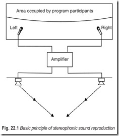
The basic principal of stereophonic sound reproduction is illustrated in Fig.22.1.
SUM AND DIFFERENCE OF SIGNALS
Although the (L + R) signal is all the listener to a monophonic program needs, the proper reception and reproduction of stereo programs requires the use of an additonal (L–R) signal. This signal is produced at the transmitter by inverting (phase changing by 180 degrees) the R signal (making it negative, or –R) and adding it in its negative form to the L signal. The resulting (L–R) signal, as well as the (L+R ) signal, are transmitted on the f.m. broadcast carrier. The two signals are received and separated at the receiver. Then, in the stereo receiver, they are added together to form the L signal alone, and the (L–R) signal is subtracted from the (L+R) signal to form the R signal alone. This is shown mathematically as follows :
(L+R) + (L–R) = L+L+R–R = 2L …(22.1)
(L+R) – (L–R) = L+R–L+R = 2R …(22.2)
STEREO MULTIPLEX MODULATION SIGNAL
The (L+R) and (L–R) signals are both sent as part of the modulation signal which frequency modulates the main (radio frequency) carrier. As far as the main carrier of the FM signal is concerned there is only one composite modulating signal, all of whose components modulate the carrier. The composition of this modulation signal includes the subcarrier, (L+R) signal, (L–R) signal, and certain other components within this overall modulating signal.
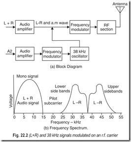
To an ordinary f.m. receiver, only a mono signal is being transmitted. Actually, additional information to which an ordinary f.m. receiver is unresponsive is also being transmitted. To explain this additional transmitted information, let us consider the effect of adding a 38 kHz carrier, as shown in Fig. 22.2. Both the (L+R) signal and the 38 kHz carrier are frequency modulated in the r.f. carrier. However, only the (L+R) signal can be reproduced at the FM receiver. That is, the 38 kHz carrier is out of the range of audibility. This is the fundamental multiplex transmitting principle.
If amplitude modulation is impressed on the 38 kHz carrier, this modulated signal will be inaudible on an ordinary FM receiver. With reference to Fig. 22.2 (a), the (L+R) signal is frequency modulated on the r.f. carrier. In addition, an audio signal, A2, is amplitude modulated on the 38 kHz carrier. This amplitude modulation produces sidebands, and the r.f. carrier is modulated by these sidebands along with the (L+R) signal. Fig 22.2 (b) shows the frequency spectrum of the modulating waveforms. The (L+R) signal has frequencies upto 15 kHz, the carrier has frequencies in the range from 23 kHz to 53 kHz. This represents an audio frequency range upto 15 kHz.
The spectrum of the modulating signal is shown in Fig. 22.2 (b). Its bandwidth is from 50 Hz to 75 kHz, the 75 kHz deviation of the carrier is the total range and limit of signal component frequencies allowed within the modulating signal.
The lowest portion of the modulating signal spectrum extends from 50 Hz to 15 kHz, and this range includes the component of the (L+R) signal, or the signal that corresponds to or may be used as a normal monophonic modulating signal. In other words, if we remove all the signal components of frequencies above 15 kHz, we have a signal similar in effect to those signals used before stereo multiplex was developed.
Next in the spectrum is a 19 kHz pilot signal. Let us ignore this for the moment and proceed to the (L–R) portion of the signal, extending from 23 kHz to 53 kHz except for a 100 Hz quiet spot in the middle. This region consists of the sidebands resulting when the (L–R) signal modulates the 38 kHz subcarrier. At the station, after modulation has taken place, the 38 kHz subcarrier is suppressed and only the sidebands are used. Since the carrier component was at 38 kHz, the (L–R) signal sidebands extend to 38 kHz + 15 kHz (23,000 Hz to 37,950 Hz and from 38,050 Hz to 53,000 Hz). These sidebands (the L–R signal) are added to the modulating signal. In relation to the main carrier, all frequencies in this composite modulation of the main carrier are above audibility, so they do not interfere with transmission and reception of the main-carrier (L+R) signal for the listener using a monophonic receiver.
The (L–R) sidebands, as an independent signal, are not intelligible (until decoded for the stereo listener) in the form in which they appear in the modulation signal. They must be: (1) recombined with a 38 kHz carrier (2) demodulated from the carrier, and (3) decoded.
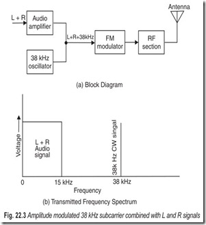
To process the signal at the receiver, the composite frequency-modulated signal depicted by Fig. 22.3(b)
must be demodulated from the main carrier and the (L+R) and (L–R) sidebands separated from the other parts of the signal by filters.
Of course, only the (L+R) signal is reproduced by an ordinary f.m. receiver. In other words, the frequencies from 23 kHz to 53 kHz will be rejected by the audio system in an ordinary f.m receiver; even if an extended range audio amplifier were used, the reproduced tones would be inaudible to the ear. In multiplex terminology the frequencies from 23 kHz to 53 kHz are said to be encoded in the radiated FM signal. Let us see how the encoded signal is recovered.
DEMODULATING THE (L–R) SIGNAL
The carrier with which the sidebands are combined at the receiver must have the desired 38 kHz frequency within very close limits and remain synchronised to prevent distortion when these sidebands are demodulated. The desired synchronisation is provided by the 19 kHz pilot carrier added to the modulation signal. This steady 19 kHz unmodulated signal is demodulated from the main carrier at the receiver and passed through a frequency doubler, whose output at 38 kHz is combined with the (L–R) signal. The output from the double R may be used directly for combining with the sideband, or as in some designs, this output can be used to synchronise a 38 kHz oscillator whose output is in turn used to combine with the sidebands.
When the 38 kHz subcarrier has been combined with the (L–R) signal sidebands, the result is an amplitude modulated signal. It can be shown that the top and bottom envelopes of the modulated signal waveforms have the waveshapes of the L and R signals respectively. A detector that operates half-wave on only the positive peaks produces only the L signal; in the same way, a negative peak detector will pickoff the R signal. Some stereo receivers (or adapters) use this method of demodulation.
In others, the signal is demodulated from the 38 kHz carrier by an ordinary a.m. detector to obtain the (L–R) signal. The (L–R) signal is then matrixed with the (L+R) signal to obtain the separate L and R signals.
In a third method of detection, the local 38 kHz subcarrier is used as a switching signal, connecting the output of the detector to the L output channel during the time of positive peaks and connecting the output of the detector to the R output channel during the time of negative peaks.
FM MULTIPLEX DETECTOR CIRCUITS
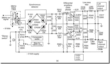
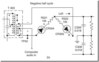
The FM stereo detector circuit shown in Fig. 22.4 (a), uses time-division multiplex detection. Basically, this system permits sampling of left and right information, each being channeled to its respective output circuit.
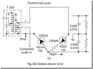
In operation, the 38 kHz signal from the secondary of the transformer is applied to the detector diode quad. This is a strong signal, some 30 times the level of the composite signal which comprises the other input to the detector. The 38 kHz switching signal causes the detector to conduct on alternate half cycles to each of the L and R outputs of the detector. Normal audio signals, (L+R), are simply interrupted at a 38 kHz rate; each output therefore contains equal amounts of (L+R) signal. In the case of (L–R) information, (which is already changing its polarity from minus to plus at a 38 kHz rate) each output of the detector contains a specific polarity of detected (L–R) information.
In the schematic, the junction of R321 and R322 represents the predominantly left output, the junction of R319 and R323 represents the predominantly right output.
At the left channel output of the detector, (L+R) appears in addition to the detected positive (L–R), therefore, the output represents left information. At the right channel output, (L+R) and the negative (L–R) appear, giving right channel information.
The predominantly left and right audio channels are fed to their respective amplifiers, Q305 and Q306. These are common-emitter amplifiers with the added feature of a tie between the two emitters. This connection permits some improvement in the separation between channels. The amplifiers are able to cancel some of the audio information which is equal in both channels, leaving more independently left and right audio at the outputs.
Balance control R337 is adjusted to vary the amount of cancellation. This circuit compensates to some extent for the imperfect balance in the synchronous detector.
One characteristic of the composite audio signal is that the sideband information surrounding the suppressed 38 kHz carrier (L–R) is constantly changing its polarity at a 38 kHz rate. The synchronous detector makes use of this fact in producing left and right audio outputs. The input to the detector bridge is 38 kHz from the transformer T303plus composite audio from the emitter of Q301, the first 19 kHz amplifier.
We first consider a 38 kHz signal of negative polarity applied to the detector, as represented by Fig. 22.4 (b). The upper two diodes (CR304 and CR305) conduct, effectively connecting the left output to the centre tap of T303. This connection allows (L+R) and the detected + (L–R) to appear at the left output of
the detector quad. Right information then cancels and predominantly left audio is delivered to the left channel output circuit.
When a positive polarity 38 kHz signal is present, as represented by Fig. 22.4 (c), the lower two diodes conduct. In this case, the right output is tied to the centre tap of T303. The (L–R) sideband information also reverses polarity and the signals at the output of the detector are (L+R) and the detected –(L–R), giving left cancellation and predominantly right channel output.
When the pilot signal falls below 6 per cent or when monophonic signals are present, the stereo indicator light goes out and –9V is applied to the centre tap of T303. This causes the detector quad to conduct through CR305 and CR303, thereby connecting equal amounts of audio to both output channels.
STEREO DECODER CIRCUIT
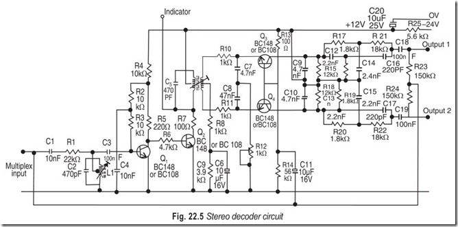
The circuit diagram of decoder is shown in Fig. 22.5. The pilot tone is extracted from the multiplex input by means of a 19 kHz circuit immediately following the discriminator output. The pilot tone is then amplified by the first transistor and applied to the base of the second transistor. The second transistor is biased to operate in Class B; that is, only the positive half cycles of the amplified tone are amplified. The distorted waveform resulting from this type of amplification is very rich in second harmonic content, and this second harmonic (38 kHz) is extracted by means of a tuned circuit at the collector of the second transistor. The peak-to-peak amplitude of the 38 kHz signal, between the collector end of the coil and the tap on the coil, is limited to approximately twice the supply voltage, hence its amplitude is constant regardless of the input level once a certain value has exceeded.
A centre tapped secondary windings applies antiphase switching signals to the emitters of the two transistors and the complete multiplex informationis applied to their bases. With this arrangement, synchronous detection to obtain the “difference” signal, alongwith matrixing of the sum or difference signals, occurs and the two separated left and right-hand signals appear—one at each collector. With a simple decoder operating on the principle described, only a limited separation is obtainable. So arrangements have been made in the design of the circuit shown in Fig. 22.5 to improve the separation. This is done by deliberately introducing a certain amount of cross-talk into the two outputs in antiphase to the inherent cross-talk, thereby cancelling the cross-talk.
Conventional de-emphasis occurs in the collector circuits of the two switching transistors but this is insufficient to remove the 38 kHz waveform from the output. As the 38 kHz waveform is of sufficient amplitude to constitute a nuisance, in that it may give rise to distortion in any following audio amplifier or to beating with the oscillator frequency of a tape recorder, it is removed by passing each output through a parallel-T filter tuned to 38 kHz. This does have a slight adverse effect on the de-emphasis but it is kept within acceptable limits.
In the absence of the 38 kHz switching waveform at the emitters of the two switching transistors, they are biased to operate in class A and any signal applied to their bases is reproduced at their collectors. The circuit is therefore compatible, requiring no switching between mono and stereo operation.
The input impedance of the decoder is approximately 15 kΩ and the decoder may be fed directly from a semiconductor discriminator capable of providing a loaded output with a peak-to-peak amplitude of approximately 750 mV. Each of the audio amplifiers into which the outputs of the decoder are fed must have an input impedance of not less than 50 kΩ.
STEREO INDICATOR
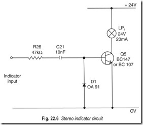
A stereo indicator gives a visual indication when a stereo transmission is in progress. It is also essential for the alignment of the decoder if only a limited amount of test equipment is available. A stereo indicator circuit using a single transistor is shown in Fig. 22.6.
The stereo indicator circuit operates by detecting the 38 kHz signal generated when the 19 kHz pilot tone is passed through the frequency doubling circuit in the decoder. This 38 kHz signal is fed through a limiting resistor and blocking capacitor to a shunt rectifier. The voltage derived from this shunt rectifier is applied to the base of a transistor. The transistor remains cut off when the signal is absent and is turned on when it is present. Therefore, the bulb in the collector circuit glows when a stereophonic broadcast is in progress but remains extinguished when a monophonic transmission is being received.
On most f.m. tuners, the stereo indicator lights upon detection of the 19 kHz pilot tone. However, this need not mean that the program is actually stereophonic, since the pilot tone is often transmitted with mono programs also. A similar situation exists on stereo amplifiers, where the stereo l.e.d. is simply controlled from the mono-stereo switch.
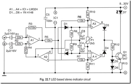
The l.e.d. based stereo indicator illustrated in Fig. 22.7 lights only when the true stereo signal is fed to the inputs. Differential amplifier A1 raises the difference between the L and R input signals. When these are equal, the output of A1 remains at the same potential as the output of A2, which forms a virtual ground rail at the half the supply voltage. When A1 detects a difference between the L and R input signals it supplies a positive or negative voltage with respect to the virtual ground rail, and so causes C3 to be charged via D1 or C4 via D2. The resistors ensure slow discharging to bridge brief silent periods in the program. Comparator A3–A4 switches on the l.e.d. driver via OR circuit D3–D4.
When building the circuit into an amplifier care should be taken to select the right point from which the input signals are obtained. In general, this should be before the volume and balance controls but behind the mono-stereo selector. The signal level should not be less than 100 mV to compensate for the drop across D1 or D2. Also observe that the impedance at the selected “tap” location is relatively low. Should the stereo light come on when a mono program is being received the input signals are different, and the sensitivity of one of the amplifier channels should be altered. If this is impossible or undesirable, R3 may be replaced by a series connected preset and a resistor.
The sensitivity of the stereo indicator is adjustable with P1. The current consumption is less than 7 mA when the l.e.d. is off, and about 20 mA when it is on.
EXERCISES
Descriptive Questions
1. What are the objectives of stereo multiplex?
2. Give the details of stereo multiplex modulation signal.
3. How the (L–R) signal is recovered?
4. Explain the working of a stereo multiplex detector circuit.
5. What is the significance of a stereo indicator and how does it function?
6. Standard multiplex transmissions are compatible. Explain.
Fill in the Blanks
1. The stereo signal consists of two audio waveforms that vary…………………………………. in frequency and amplitude.
2. Standard multiplex transmissions are…………………………………. .
3. Both signals are modulated onto the same carrier by means of…………………………………. provided in the system.
4. The 38 kHz carrier is out of the range of…………………………………. .
5. The (L–R) signal is…………………………………. with the (L+R) signal to obtain the separate L and R signals.
6. The FM stereo detector circuit uses…………………………………. detection.
7. A stereo indicator gives a…………………………………. indication when a stereo transmission is in progress.
8. Stereo indicator remains…………………………………. when a monophonic transmission is on.
ANSWERS
Fill in the Blanks |
||
|
1. independently |
2. compatible |
3. interleaving |
|
4. audability 7. visual |
5. matrixed 8. glowing |
6. time division multiplex |
