Solid-state switches
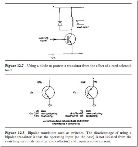
The subject of solid-state switching could fill several books, and in this chapter we are concerned more with selection and use than with theory. In addition, the more specialized types of electronic switches were dealt with in the previous chapter. The fundamental principles of solid-state switching are that a transistor (bipolar or FET) has a low-impedance state and a high-impedance state, and can be switched from one state to another with a small change of voltage. The bipolar transistor (Figure 12.8) has a high impedance between collector and emitter when the base terminal is at the emitter voltage or up to 0.5 V above the emitter voltage (‘above’ in
this sense meaning closer to collector voltage). ;\’hen the base voltage is (for a silicon transistor) above about 0.55 V then the collector-emitter path becomes conducting. In this respect the transistor acts like a form of relay. There are, however, two snags. One is that the conductivity is one way from collector to emitter only; the other is that the base to emitter circuit conducts at the same time as the collector to emitter circuit conducts. This makes it completely impossible to isolate the switched circuit from the con- trolling circuit.
The use of bipolar transistors in signal-switching circuits is therefore a matter of careful design, making use of bridge circuits. Since the base voltage can be DC and can be decoupled, the bipolar transistor bridge can be used to switch signal circuits by means of a low-voltage DC supply to the bases. In general, though, bipolar transistors are used more for DC switching than for signal purposes. This is because the minimum collector
to emitter voltage is around 0.2 V, so that signal amplitudes of less than that amount do not pass through the switch. For low-level signals, then, this causes an unacceptable amount of signal waveform distortion.
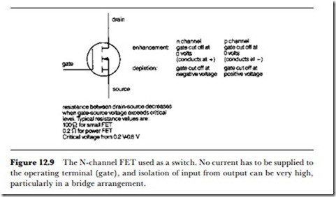
The use of FETs, particularly the MOSFET type (Figure 12.9), for signal switching is much simpler and more frequently encountered. The resistance between the source and the drain is governed by the voltage at the gate, and the gate is almost completely isolated electrically from the other two electrodes. In addition, current will flow between source and drain even when the voltage difference is very low, and the geometry of the device can be such that current will continue to flow even if the polarity is reversed (provided that the gate voltage is maintained).
Once again, bridge or two-transistor circuits are normally used, and the complete arrangement is available in IC form, usually as dual or quad single-pole single-throw switches – Figure 12.10 shows some typical characteristics. Switches of this type can be used with fast-changing waveforms such as video signals, and have only negligible switching transients. They are also widely used in audio preamplifiers because they permit switching that is free of the usual transients, and are extremely useful for switching data signals.

