RECORDING LEVEL INDICATORS
A casual glance at the front panels of most of the new cassette tape decks and even a few of the latest reel-to-reel tape recorders would give the impression that the VU meter is on its last legs. There are all manner of new indicating devices, many of them based upon the use of light emitting diodes, others using new fluorescent indicating bars or lights, and ever a few resorting to electro- mechanical movements which employ the old- fashioned meter needle, but which purport to be peak-reading devices.
VU METERS
Of all the VU meters seen over the last several years, only a very few were actually VU meters. A true VU meter is a relatively expensive device which, if incorporated into such consumer products as cassette tape decks, would substantially add to the cost of those products. In other words, most of the so called VU meters found in such tape decks are not truly VU meters at all. A true VU meter, developed by broadcast and television engineers is nothing more than a rectifier ac type voltmeter which responds to signal level components whose amplitude lies somewhere between the average and the peak values of a complex waveform. In order to comply with the existing standards, it should take the meter’s pointer or indicator somewhere between 270 and 330 milliseconds to reach 99 per cent of full deflection in response to a tone that is suddenly applied. Overshoot of the steady-state value of that tone should not exceed the steady-state value by more than 1.0 to 1.5 per cent and the decay time required for the pointer to reach its neutral or rest position, when the tone is removed, should be close to the rise time.
From the above description, it should be obvious that even a correctly constructed VU meter cannot possibly display or register short term peaks that invariably occur in voice and music program material. In broadcast circles, it is generally assumed from long experience that peaks in musical programming are likely to be about 10 dB higher than the VU meter indicates, although with certain types of program material, peaks as high as 20 dB greater than the VU meter readings have been observed. These generalisations apply fairly well if we are talking about true VU meters whose movements have the precise ballistics mentioned earlier. As we have indicated, most cassette tape decks that employ mechanical-pointer type metering systems may label those meters with the term “VU” but such labelling is incorrect. In fact, there is no telling what the ballistics or rise time of these low-cost so called VU meters might be, since there is a great deal of variation in characteristics of these meters from one manufacturer of decks to another and even from model to model. A typical VU meter is illustrated in Fig. 13.1 .
PEAK READING METERS
The first significant departure from the erroneously-dubbed VU meters found on home type tape decks, occurred when the rather critical parameters of slow-speed cassette tape decks and tape made it essential to supply a faster responding meter to home recordists who would otherwise run the gain or recording level up too high. While reel-to-reel tape decks, operating at higher tape speeds and utilising wider tape, generally have a fair amount of headroom or “margin for over-recording”, the same is not true when it comes to slow- speed cassette taping where even a slight amount of over-recording causes high levels of distortion during playback of the tape. Mechanical peak-reading record-level meters, though faster responding than true VU meters or pseudo-VU meters found on earlier cassette tape recorders are, nevertheless, incapable of responding instantaneously to fast variations in level which are often found in music wave forms. Any mechanical meter movement and pointer arrangement has a fair amount of inertia which prevents the meter pointer from moving that quickly.
Still, the peak reading mechanical meters were an improvement over the earlier sluggish meter movements. Even in professional circles, however, there are those who maintain that the VU meter still serves a useful and important purpose. There are now some tape decks which employ quasi-VU meters (with non-standardised ballistics) that also incorporate a single peak-indicating l.e.d. either within the meter face area or elsewhere on the front panel of the tape deck. The VU meter continues to indicate some level between average and peak, while the sole purpose of that single l.e.d. is to indicate peaks that might overload the tape recording medium. The trouble with this arrangement is that when the overload l.e.d. flashes, the user has no way of knowing how much over-recording has occurred. Of course, the over-recording damage has already taken place by the time the flashing l.e.d. is observed. Since an unknown difference in level between the VU meter readings and the peak amplitudes exists, the user has no way of predicting when overload will occur and cannot take the correct remedial or preventive action (reducing recording levels in a smooth and imperceptible manner).
PEAK READING LED METERS
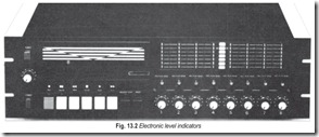
Totally electronic level indicators, Fig. 13.2 have found their way into the front panels of tape decks as well as audio amplifiers and other components in the last decade. The l.e.d. is a relatively inexpensive device, and even if a manufacturer uses several of them for a metering system on a cassette deck, the part’s cost is not significantly greater than that which would have to be spent for a medium quality quasi-VU meter. A bank of l.e.d.’s., Fig. 13.3, substituting for an electro-mechanical meter offers many obvious advantages. Although back-up electronics is needed for driving the individual l.e.d’s and causing them to illuminate progressively at different signal levels, the physical spacing between l.e.d.’s can be linearly configured, so that each dB (or 2 dB or 3 dB) mark is as far away from the previous indicator as it is from the succeeding one. Visually, such an arrangement is easier to read than the usually compressed scale of the quasi-VU meter which it replaces.
Since the l.e.d. metering system is electronically driven, it is also possible to offer the equivalent rise and decay times (ballistic) of actual VU meters, either as an optional mode of use or as the sole mode. In other words, the electronically driven l.e.d. metering system can serve as either a true peak indicator or as a VU meter (see Fig. 13.3). Response time of the l.e.d., when electronically driven, can be so fast that it is actually necessary to slow it down (even in the peak-reading mode) to a few milliseconds so that the human eye can perceive it and allow the brain to interpret what the eye sees.
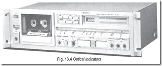
The so called fluorescent indicator metering systems, Fig. 13.4 are simply variations of the l.e.d. – indicator principle and can also be used to indicate true VU levels or peak levels, with whatever rise time the desinger decides is appropriate. Both of theseall-electronic indicating systems have another distinct advantage. A third function, known as peak-hold, can be easily incorporated into the electronic circuitry that drives these displays. The advantage of the peak hold mode is that if a user wishes to make certain that the program to be transcribed into tape never causes over-recording, the recordist can audition the entire program, from start to finish, using the peak-hold feature to determine where, and how great, the loudest sounds of the program material are. Gain controls can then be lowered appropriately to accommodate that peak level in advance and the entire recording can then be transcribed without the need for any “gain riding” or compression while the recording is actually taking place.
ZERO dB LEVEL
One might think that with such easy-to-read electronic metering systems now available to cassette deck manufacturers that all would be well and that everyone ought to be able to record with equal professionalism regardless of which machine is used. Unfortunately, that’s not true either. In the days when cassette decks used those quasi-VU meters exclusively, the ballistics of the meter were not the only thing that wasn’t standard from unit to unit. Neither was the recording level which corresponded to “0 dB” on the meters. Unfortunately, thatlack of standardisation has persisted to this day, even though the meters and their usefulness have improved with the advent of electronic metering.
Recording level indication, at least as applied to magnetic tape, is usually described quantitatvely in terms of nanowebers-per-metre (abbreviated nWb/m). Louder sounds to be recorded, when translated into magnetic flux which is used to magnetise the tape’s ferric oxide particles, result in more nWb/m than do softer sounds. Those familiar with the Dolby noise reduction system know that the reference Dolby level for Dolby-B systems as applied to cassette tape decks is 200 nWb/m, and Dolby maintains that reference level would be a convenient one to call the “0 dB” level.
If you have examined metering systems on different cassette decks, you will have noticed that often the Dolby calibration point on the meters (usually in the form of a pair of “D’s”, back-to-back) is inscribed at what corresponds to +3 dB, or at 0 dB or in a few rare instances actually below 0 dB. That means that not everyone is calibrating meters in the same way. So, even if we were to assume that with the coming of totally electronic record level metering systems all of these meters would respond in a similar fashion in so far as attack and decay times are concerned, we would still be faced with an incompatibility between various meters on different decks which use different magnetisation levels as their “0 dB” points.
Why do some manufacturers choose 0 dB points that are lower than 200 nWb/m? Probably because they believe that in doing so they are protecting their customers from the evils of over-recording. If the user thinks that 0 dB on his or her meters is the highest permitted recording level, then even if that level is occasionally exceeded accidentally, the tape will not be saturated and the user will come away thinking that the machine has great headroom ! The truth, of course, is that the 0 dB point was deliberately shifted to correspond with a lower magnetisation level and, if the user stays scrupulously at or below 0 dB, he or she will suffer signal-to-noise degradation and will not be utilising the full dynamic range of which the deck/ tape combination is actually capable of.
Conversely, the deck maker who calibrated 0 dB at a point somewhere above 200 nWb/m does so in an attempt to impress the user with “how loud a recording” he or she will get when simply peaking the meters at 0 dB from time to time. The user comes away thinking that the machine is very “sensitive”, but of course, 0 dB in this case is very close to the overload point of the machine/tape combination. Now that metering systems have been improved on cassette decks, it would seem to be time to standardise how those meters are calibrated. Only then will it be fair to say that the cassette tape medium is a universal one, and one that permits interchangeability from machine to machine and from tape to tape.


