MOTOR CHARACTERISTICS
Static torque–displacement curves
From the previous discussion, it should be clear that the shape of the torque–displacement curve, and in particular the peak static torque, will depend on the internal electromagnetic design of the rotor. In particular the shapes of the rotor and stator teeth, and the disposition of the stator windings (and permanent magnet(s)) all have to be optimised to obtain the maximum static torque.
We now turn to a typical static torque–displacement curve, and look at how it determines motor behaviour. Several aspects will be discussed, including the explanation of basic stepping (which has already been looked at in a qualitative way); the inXuence of load torque on step position accuracy; the eVect of the amplitude of the winding current; and half-step and mini-stepping operation. For the sake of simplicity, the discussion will be based on the 308 per step 3-phase VR motor introduced earlier, but the conclusions reached apply to any stepping motor.
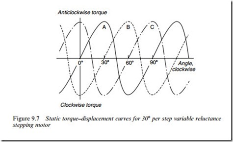
Typical static torque–displacement curves for a 3-phase 308 per step VR motor are shown in Figure 9.7. These show the torque that has to be
applied to move the rotor away from its aligned position. Because of the rotor–stator symmetry, the magnitude of the restoring torque when the rotor is displaced by a given angle in one direction is the same as the magnitude of the restoring torque when it is displaced by the same angle in the other direction, but of opposite sign.
There are three curves in Figure 9.7, one for each of the three phases, and for each curve we assume that the relevant phase winding carries its full (rated) current. If the current is less than rated, the peak torque will be reduced, and the shape of the curve is likely to be somewhat diVerent. The convention used in Figure 9.7 is that a clockwise displacement of the rotor corresponds to a movement to the right, while a positive torque tends to move the rotor anticlockwise.
When only one phase, say A, is energised, the other two phases exert no torque, so their curves can be ignored and we can focus attention on the solid line in Figure 9.7. Stable equilibrium positions (for phase A excited) exist at u ¼ 08, 908, 1808 and 2708. They are stable (step) positions because any attempt to move the rotor away from them is resisted by a counteracting or restoring torque. These points correspond to positions where successive rotor poles (which are 908 apart) are aligned with the stator poles of phase A, as shown in Figure 9.5(a). There are also four unstable equilibrium positions, (at u ¼ 458, 1358, 2258 and 3158) at which the torque is also zero. These correspond to rotor positions where the stator poles are midway between two rotor poles, and they are unstable because if the rotor is deXected slightly in either direction, it will be accelerated in the same direction until it reaches the next stable position. If the rotor is free to turn, it will therefore always settle in one of the four stable positions.
Single-stepping
If we assume that phase A is energised, and the rotor is at rest in the position u ¼ 08 (see Figure 9.7) we know that if we want to step in a clockwise direction, the phases must be energised in the sequence ABCA, etc., so we can now imagine that phase A is switched-oV, and phase B is energised instead. We will also assume that the decay of current in phase A and the build-up in phase B take place very rapidly, before the rotor moves signiWcantly.
The rotor will Wnd itself at u ¼ 08, but it will now experience a clockwise torque (see Figure 9.7) produced by phase B. The rotor will therefore accelerate clockwise, and will continue to experience clockwise torque, until it has turned through 308. The rotor will be accelerating all the time, and it will therefore overshoot the 308 position, which is of course its target (step) position for phase B. As soon as it overshoots, however, the torque reverses, and the rotor experiences a braking torque, which brings it to rest before accelerating it back towards the 308 position. If there was no friction or other cause of damping, the rotor would continue to oscillate; but in practice it comes to rest at its new position quite quickly in much the same way as a damped second- order system. The next 308 step is achieved in the same way, by switching-oV the current in phase B, and switching-on phase C.
In the discussion above, we have recognised that the rotor is acted on sequentially by each of the three separate torque curves shown in Figure Alternatively, since the three curves have the same shape, we can think of the rotor being inXuenced by a single torque curve, which ‘jumps’ by one step (308 in this case) each time the current is switched from one phase to the next. This is often the most convenient way of visualising what is happening in the motor.
Step position error and holding torque
In the previous discussion the load torque was assumed to be zero, and the rotor was therefore able to come to rest with its poles exactly in line with the excited stator poles. When load torque is present, however, the rotor will not be able to pull fully into alignment, and a ‘step position error’ will be unavoidable.
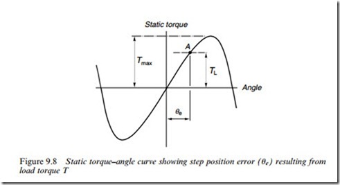
The origin and extent of the step position error can be appreciated with the aid of the typical torque–displacement curve shown in Figure 9.8. The true step position is at the origin in the Wgure, and this is where the rotor would come to rest in the absence of load torque. If we imagine the rotor is
initially at this position, and then consider that a clockwise load (TL) is applied, the rotor will move clockwise, and as it does so it will develop progressively more anticlockwise torque. The equilibrium position will be reached when the motor torque is equal and opposite to the load torque,
i.e. at point A in Figure 9.8. The corresponding angular displacement from the step position (ue in Figure 9.8) is the step position error.
The existence of a step position error is one of the drawbacks of the stepping motor. The motor designer attempts to combat the problem by aiming to produce a steep torque–angle curve around the step position, and the user has to be aware of the problem and choose a motor with a suYciently steep curve to keep the error within acceptable limits. In some cases this may mean selecting a motor with a higher peak torque than would otherwise be necessary, simply to obtain a steep enough torque–angle curve around the step position.
As long as the load torque is less than Tmax (see Figure 9.8), a stable rest position is obtained, but if the load torque exceeds Tmax, the rotor will be unable to hold its step position. Tmax is therefore known as the ‘holding’ torque. The value of the holding torque immediately conveys an idea of the overall capability of any motor, and it is – after step angle – the most important single parameter, which is looked for in selecting a motor. Often, the adjective ‘holding’ is dropped altogether: for example ‘a 1-Nm motor’ is understood to be one with a peak static torque (holding torque) of 1 Nm.
Half stepping
We have already seen how to step the motor in 308 increments by ener- gising the phases one at a time in the sequence ABCA, etc. Although this ‘one-phase-on’ mode is the simplest and most widely used, there are two other modes, which are also frequently employed. These are referred to as the ‘two-phase-on’ mode and the ‘half-stepping’ mode. The two- phase-on can provide greater holding torque and a much better damped single-step response than the one-phase-on mode; and the half-stepping mode permits the eVective step angle to be halved – thereby doubling the resolution – and produces a smoother shaft rotation.
In the two-phase-on mode, two phases are excited simultaneously.
When phases A and B are energised, for example, the rotor experiences torques from both phases, and comes to rest at a point midway between the two adjacent full step positions. If the phases are switched in the sequence AB, BC, CA, AB, etc., the motor will take full (308) steps, as in the one-phase-on mode, but its equilibrium positions will be interleaved between the full step positions.
To obtain ‘half stepping’ the phases are excited in the sequence A, AB, B, BC, etc., i.e. alternately in the one-phase-on and two-phase-on modes. This is sometimes known as ‘wave’ excitation, and it causes the rotor to advance in steps of 158, or half the full step angle. As might be expected, continuous half stepping usually produces a smoother shaft rotation than full stepping, and it also doubles the resolution.
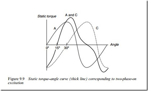
We can see what the static torque curve looks like when two phases are excited by superposition of the individual phase curves. An example is shown in Figure 9.9, from which it can be seen that for this machine, the holding torque (i.e. the peak static torque) is higher with two phases excited than with only one excited. The stable equilibrium (half-step) position is at 158, as expected. The price to be paid for the increased holding torque is the increased power dissipation in the windings, which is doubled as compared with the one-phase-on mode. The holding torque increases by a factor less than two, so the torque per watt (which is a useful Wgure of merit) is reduced.
A word of caution is needed in regard to the addition of the two separate one-phase-on torque curves to obtain the two-phase-on curve. Strictly, such a procedure is only valid where the two phases are mag- netically independent, or the common parts of the magnetic circuits are unsaturated. This is not the case in most motors, in which the phases share a common magnetic circuit, which operates under highly saturated conditions. Direct addition of the one-phase-on curves cannot therefore be expected to give an accurate result for the two-phase-on curve, but it is easy to do, and provides a reasonable estimate.
Apart from the higher holding torque in the two-phase-on mode, there is another important diVerence which distinguishes the static be- haviour from that of the one-phase-on mode. In the one-phase-on mode, the equilibrium or step positions are determined solely by the geometry of the rotor and stator: they are the positions where the rotor and stator are in line. In the two-phase-on mode, however, the rotor is intended to come to rest at points where the rotor poles are lined-up midway between the stator poles. This position is not sharply deWned by the ‘edges’ of opposing poles, as in the one-phase-on case; and the rest position will only be exactly midway if (a) there is exact geometrical symmetry and, more importantly (b) the two currents are identical. If one of the phase currents is larger than the other, the rotor will come to rest closer to the phase with the higher current, instead of halfway between the two. The need to balance the currents to obtain precise half stepping is clearly a drawback to this scheme. Paradoxically, how- ever, the properties of the machine with unequal phase currents can sometimes be turned to good eVect, as we now see.
Step division – mini-stepping
There are some applications (e.g. in printing and phototypesetting) where very Wne resolution is called for, and a motor with a very small step angle – perhaps only a fraction of a degree – is required. We have already seen that the step angle can only be made small by increasing the number of rotor teeth and/or the number of phases, but in practice it is inconvenient to have more than four or Wve phases, and it is diYcult to manufacture rotors with more than 50–100 teeth. This means it is rare for motors to have step angles below about 18. When a smaller step angle is required a technique known as mini-stepping (or step division) is used.
Mini-stepping is a technique based on two-phase-on operation which provides for the subdivision of each full motor step into a number of ‘substeps’ of equal size. In contrast with half stepping, where the two currents have to be kept equal, the currents are deliberately made un- equal. By correctly choosing and controlling the relative amplitudes of the currents, the rotor equilibrium position can be made to lie anywhere between the step positions for each of the two separate phases.
Closed-loop current control is needed to prevent the current from changing as a result of temperature changes in the windings, or vari- ations in the supply voltage; and if it is necessary to ensure that the holding torque stays constant for each ministep both currents must be changed according to a prescribed algorithm. Despite the diYculties referred to above, mini-stepping is used extensively, especially in photographic and printing applications where a high resolution is needed. Schemes involving between 3 and 10 ministeps for a 1.88 step motor are numerous, and there are instances where up to 100 ministeps (20 000 ministeps/rev) have been successfully achieved.
So far, we have concentrated on those aspects of behaviour, which depend only on the motor itself, i.e. the static performance. The shape of the static torque curve, the holding torque and the slope of the torque curve about the step position have all been shown to be import- ant pointers to the way the motor can be expected to perform. All of these characteristics depend on the current(s) in the windings, however, and when the motor is running the instantaneous currents will depend on the type of drive circuit employed, as discussed in the next two sections.


