COLOUR TV STANDARDS AND SYSTEMS
Colour television has considerably complicated the variables between different television systems. The systems used for television have been thoroughly standardised. There are three different incompatible systems for encoding signals. These three systems are used in different parts of the world. There are various steps in the processing of the video signal. These steps do not necessarily have to be the same in different countries, or not even in the same country, but the end result would always be the same.
DISPERSION AND RECOMBINATION OF LIGHT
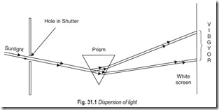
If a stream of sunlight is made to pass through a small circular hole in one of the shutters, it will make a small circular patch on the opposite wall. On placing a triangular prism before the hole, an elongated coloured patch of light will be formed on the wall. This is called the spectrum of light. The colours formed are in the order shown in Fig. 31.1
White light consists of a mixture of seven different colours. The refractive index of glass is different for each colour, so that when white light falls on the prism, each colour in it is refracted at a different angle, with the result that the colours are spread out to form a spectrum.
When white light is incident on the prism it is refracted towards the base of the prism, the violet being deviated the most and the red the least. The separation of white light into its component colours by a prism is called dispersion. Strictly speaking there are many shades of each colour in the spectrum, each shade gradually merging into the next.
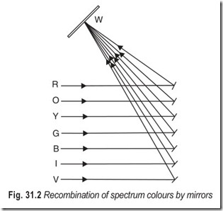
The colours of the spectrum may be recombined to form white light by allowing the spectrum to be formed on a row of small rectangular plane mirrors, Fig. 31.2. On adjusting the angle which the mirrors make with the incident light, so that all the mirrors reflect the light to the same place on the screen, the constituent colours of white light are recombined to form a white patch of light.
When white light falls on any particular body, then either all of the colours in the white light may be reflected from the body, when it appears white, or only some of them may be reflected while the others are absorbed. In the latter case, the body appears coloured. The energy of the light absorbed is generally covered into internal energy so that the body becomes slightly warmer. The colour which the body presents to the eye is the colour of the light which it reflects. Thus the leaves of plants appear green since they reflect green light and absorb other colours. White paper reflects all the colours of the spectrum, while black absorbs all of them, Blackness is thus due to the absence of light of any colour.
PRIMARY AND SECONDARY COLOURS
Colours which cannot be produced by mixing other colours are called primary colours. It is not found possible to produce either red, blue or green colours by mixing two other colours. For this reason red, green and blue are called primary colours.
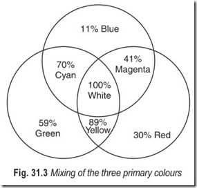
A secondary colour can be produced by mixing other colours. Thus yellow colour can be produced by mixing red and green colours. Magenta colour can be produced by mixing red and blue colours. By the same token, cyan colour can be produced by mixing blue and green colours. This is shown in Fig. 31.3.
Two colours which give white light when added together are called complementary colours. The following facts can be verified.
In colour television, red, green and blue colours are chosen, and are called primary colours. When these colours are combined with each other in various proportions, a wide range of hues and tints (colour shades) are produced. These hues and tints are sufficient for presenting any colour picture. Also the range of colours produced by combining red, green and blue colours is wider than the range produced by combining any other colours.
The colours red, green, and blue are called additive primaries and are used when coloured light sources are blended to produce the required colour. Red, yellow and blue are called subtractive primaries and are used when a picture on print is viewed by reflected light from a white source.
ATTRIBUTES OF COLOUR
All primary colours as well as those produced by adding the primary colours in suitable proportions are characterised by three main features: hue, brightness and saturation.
Hue : The colour itself is called the hue and depends on the dominant wavelength of the light. By adding two or more of the primary colours many hues are produced.
Brightness : Each colour produces a certain amount of brightness. Brightness of a colour is determined by the amount of light energy contained in it. Light energy is measured in lumens.
Saturation : The amount of white light contained in a colour determines its saturation level. For instance, a highly saturated or deep red light will contain a much less amount of white light than a dull red light. Saturation, thus denotes the degree of dilution of colour by white light. More white light makes the colour dull or less saturated or vice versa.
Brightness of a colour is quite different from its saturation. Brightness is an attribute of white light and colour light, whereas saturation is an attribute of colour light only. It is possible to vary one while keeping the other constant. Colour TV receivers, therefore, have two different controls: brightness and saturation. When the brightness control is varied, the amount of light energy contained in the colour is varied. When the saturation control is varied, the amount of white light contained in the colour is varied.
LUMINANCE SIGNAL
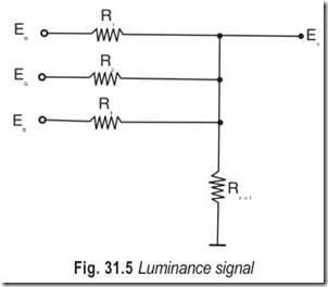
The luminance signal can be obtained by adding together the signals representing the three primaries, R, G and B. However, the three voltages contributing the luminance signal must be taken in different amounts because the human eye responds to each of the three primaries differently.Calculations show that the luminance signal associated with whites of the picture should contain 30% red, 59% green and 11% blue.
EY= 0.30 ER + 0.59 EG+ 0.11 EB …(31.3)
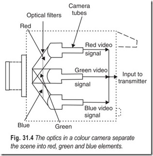
This equation, pivotal to colour television, needs some explanation, Suppose that a simple pattern made of a white stripe against a black background is projected onto photocathodes of the three pick-up tubes. The dichroic mirrors, Fig. 31.4, will split light from the white stripe into three colour components R, G and B. The gain of the video amplifiers can then be adjusted so that their output voltage is the same i.e.;
ER = EG = EB
This is the relative sensitivity of a three tube camera. The luminance signal essential to operation of a black-and-white TV, is produced by means of a matrix. The circuit of a simple matrix composed of four resistors (threevoltage dividers) is shown in Fig. 31.5. If the values of R1, R2 and R3 are chosen to be sufficiently high in comparison with Rout, the voltage dividers are mutually isolated so that the following voltages are developed across the resistor Rout:
By setting the scale factors Rout /R1 = 0.30, Rout /R2 = 0.59 and Rout /R3 = 0.11 the following luminancesignal will be secured at the matrix output :
EY = ERout + EGout + EBout
EY = 0.30 ER + 0.59 EG + 0.11 EB …(31.5)
The following example will provide a better insight into the significance of equation 31.3 to colour The following example will provide a better insight into the significance of equation 31.3 to colour television. Suppose two blue and white objects having the same intensity of radiation are to be televised. To an observer watching the two areas on a colour reproducer, both of them will appear different in luminance.
In accordance with the above equation the luminance of the blue area will be equal to 11% of that of the white area.
On a black and white reproducer the areas will not appear coloured. However due to matrixing, the luminance of the blue area will still be equal to 11% of that of the white area because of the voltages ER and EG entering the equation for EY and coming from the red and green pick-up tubes, disappear and EY = 0.11 EB.
To keep the bandwidth needed for the television signal unchanged during the insertion of the luminance signal, one of the colouring signals, ER, EG or EB should be dropped from the transmission. This may be done on the basis of equation 31.3. If the receiving terminal picks up two colour signals, say ER and EB in addition to the luminance signal, the third colouring signal EG can be derived by matrixing. It follows from the equation for EY that
EG = 1/0.59 (EY – 0.11 EB – 0.30 ER ) …(31.6)
The gain of the succeeding stages should be adjusted so as to introduce a correction factor of 1/0.59. In this way, by the use of matrixing in the receiver, it is possible to derive four signals, EY , ER , EG
and EB from three input signals, EY , ER and E B .
CHROMINANCE SIGNAL
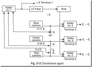
The generation of chrominance signal involves the separation of the luminance signal, EY from the natural colour signals, ER , EG and EB . This is shown in Fig. 31.6. The natural colour signals ER , EG and EB are developed across resistors R1 , R2 and R3 respectively. Part of the voltage across these resistors (0.3 V across R1 , 0.59 V across R2 , and 0.11 V across R3 ) is tapped off. The full potential difference across R1 , R2 and R3 is simultaneously fed to the adders in stages 2, 3 and 4.
When a white scene is being televised, the three pick-up tubes will extract the three primary colours from the white light and develop corresponding voltages across R1 , R2 and R3 . Since light falls on all the three pick-up tubes with the same intensity, these three voltages would be equal,ER = EG = EB = (say) 1 V Adder stage 1 will produce an output of:0.30 E+ 0.59 E+ 0.11 EThe sum of these voltages is the voltage ER corresponding to white light. As such, the output from adderstage 1, will be EG .Thus EB = 1 VThis output is routed through an L.P. filter (low pass filter) to an amplifier stage which is a conventional common-emitter amplifier, so that at its output we obtain the signal (–E ), whose value in this example will be – 1 V.
The (–EY) signal is applied simultaneously to stage 2, 3 and 4. To these stages the full voltages ER, EG and EB are also applied. In the case of white light each of these three voltages are each equal to 1 V. Thus each of the 2, 3 and 4 stages has two inputs :
–EY = – 1 V
and ER = EG = E B = 1 V
Obviously the output of each one of the adder stages 2, 3 and 4 will be zero. These four outputs are brought out from terminals 1 to 4 and routed to the TV transmitter after due processing.
This, then, is the process of televising a white scene. The luminance signal is available at terminal 1 for transmission and no signal is avialable at terminals 2, 3 and 4.
Let us next consider a colour scene, say a red scene. The red camera will generate the signal ER. Let ER, the potential drop across R1 be 1 V. Part of the voltage (0.30 V) is tapped off and applied to terminal 1. Since only a red scene is being televised, there will obviously be no output from the blue and green cameras. Hence the input to terminal 1, will be:
ER = 0.30 V; EG = 0 V and EB = 0 V
Thus, the output designated as EY will be:
EY = 0.30 V
This voltage is available at terminal 1 for being routed to the transmitter. Also, this voltage is inverted
after passing through the LP filter and a stage of amplification. After inversion, it is applied to stages 2, 3 and
4. This inverted voltage will be.
– EY = – 0.30 V
Now the input to stages 2, 3 and 4 will be :
At terminal 2 E R = 1 V and – EY = – 0.30 V
At terminal 3 E G = 0 V and – EY = – 0.30 V
GAt terminal 4 E B = 0 V and – EY = – 0.30 V
The output of the adder stages available at terminals 1 to 4 will be
At terminal 1 EY = 0.30 V
At terminal 2 E R – EY = 0.70 V
At terminal 3 E G – EY = – 0.30 V
At terminal 4 E B – EY = – 0.30 V …(31.7)
The voltage available at terminal 1 is the luminance signal EY . The voltages available at terminals 2, 3 and 4, designated as ER – E Y , E G – E Y and EB – EY respectively are the colour difference or chrominance signals.
This, in brief, is the technique adopted in the TV transmitter for electrically separating the natural colour and luminance signals, resulting in the generating of colour difference or chrominance signals.
COLOUR PICTURE TUBE
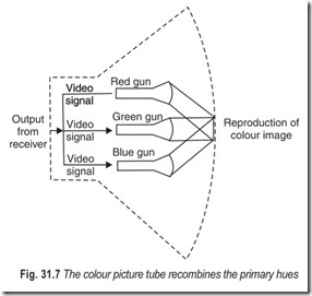
The colour television camera separates the primary hues from the televised scene, Fig. 31.4, and the colour picture tube recombines them Fig. 31.7. This is comparable to the function of a mike (which picks up the sound from the program initiator and translates it into its electrical image) and louspeaker (which retranslates electrical image produced by the mike back into its original form for the listeners).
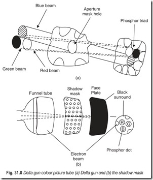
The colour picture tube is basically a tube which has three electron guns in one picture tube envelope. The three guns are placed in the neck of the tube in a triangle (delta). One gun is called the red gun, the second the blue gun and the third the green gun (see Fig. 31.8). The combinations of these primary colours produce all the other colours, including white.
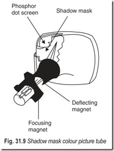
The phosphor on the screen or face plate is considerably different from the phosphor of monochorome picture tubes. Instead of a solid coating of one phosphor on the screen, each of the three phosphors is placed in dots along a horizontal axis, that is in one horizontal line, the three basic colour dots of phosphors will be placed in a triangle again and again, until the other side of the screen is reached. There are rows after rows of these triangles on the screen. They make up what is called a phosphor dot pattern. The colour tube, called the trigun tricolour tube also has a shadow mask. It ensures that the beams from the three electron guns hit their respective phosphor dots. This is shown in Fig. 31.8.
The colour tube is scannded in the same way as a black-and-white picture tube. If the picture being received is a black-and white picture all the three guns will be operating. If however, the picture being televised is in colour, the red gun will operate for red objects in the picture, green for green objects in the picture, and so on. If some other colour is required, then the proper guns will operate to mix the basic colours and produce the desired colour. The quantity of electrons hitting the phosphor dots is controlled by their respective control grids so as to produce any desired colour.
DIFFERENCE BETWEEN A MONOCHROME AND A COLOUR PICTURE TUBE
The colour picture tube differs from the monochrome picture tube in the following four aspects:
1. It has three guns which provide three electron beams, one each for the three primary colours (trigun, tricolour).
2. The screen of the colour picture tube is coated with three different types of phosphor droplets which separately emit red, green and blue light when the phosphors are bombarded by the high velocity electrons from the three guns.
3. The phosphors are embedded on the screen in a triangular dot pattern (triad). Each triad has a group of three phosphor dots.
4. The shadow mask which is accurately mounted on the face about ½ inch behind the screen is the fourth distinguishing feature between a colour picture tube and a black-and-white picture tube.
DELTA GUN AND IN-LINE GUN
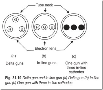
Shadow mask colour picture tubes are trigun, tricolour picture tubes with delta guns, Fig. 31.9. In picture tubes incorporating delta guns, each gun is positioned at an angle of 120° along the vertices of an equilateral triangle inscribed in a circle as shown in Fig. 31.10(a). Each gun can have the maximum possible size in the tube because of equal spacing between them. However, convergence adjustmens must correct for the guns in different planes.
In in-line guns all the three guns are in one horizontal plane angled in towards the centre. Fig. 31.10(b). For the same neck diameter, each in-line gun is smaller than each delta gun. With smaller guns, it is more difficult to obtain a high-intensity spot with sharp focus, but convergence is easier with in-line guns.
There are three types of in-line gun tubes and they have completely replaced the delta gun tubes in colour TV receivers. Some picture tubes employ one gun with three in-line cathodes, as shown in Fig. 31.10(c). These cathodes produce three electron beams that are focused and accelerated by a common gun.
COLOUR TV CAMERAS
There are two general categories of colour TV cameras; one group uses a single (special) camera tube and the other group uses three camera tubes.
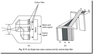
In the single-tube colour camera, Fig. 31.11, the tube face plate has a vertical stripe filter on the front of the tube and a frequency separation technique to extract the luminance and chrominance signals.
The basic camera tube is normally a vidicon with 17 mm diameter target. Unlike monochrome tubes, the colour tube has a striped colour filter bonded to its face plate just in front of the photosensitive target. In a typical tube the colour stripes may be green, cyan and clear, repeated in sequence across the face of the tube. The stripes themselves run vertically down the face of the tube and are very narrow, with typically some 300 sets of stripes across the picture area.
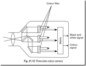
When three tubes are used, a separate tube is employed for each of the three primary colours: red, green, and blue. A colour filter system separates the incoming light from the image into the three colours and focuses each colour onto the face plate of an appropriate camera tube. The three camera tubes are identical except the photosensitive material in each tube is more responsive to the particular colour for which the tube is used.
Each colour is first determined by the filter system. The output from each tube consists of voltages that represent the elements of the particular primary colour reflected by the scene. These output are then amplified to provide three channels of video signals, one channel for each colour.
PLUMBICON CAMERA TUBE
The plumbicon, developed by Philips of Holland, is a small lightweight television camera tube that has fast response and processes high quality pictures at low light levels. Its small size and low power operating characteristics make it an ideal tube for solid-state TV cameras designed to serve a particular purpose. Modern colour television cameras are making widespread use of the plumbicon because of its simplicity and spectral response.
Functionally, the plumbicon is very similar to the standard vidicon. Focus and deflection are both accomplished magnetically. The main difference between the plumbicon and the standard vidicon is the target.As shown in part (a) of Fig. 31.13 the inner surface of the glass face plate is coated with a thin transparent conductive layer of tin oxide (SnO2 ). This layer forms the signal plate of the target. A photoconductive layer of lead monoxide (PbO) is deposited on the scanning side of the signal plate. These layers are specially prepared to function as three sub-layers. Each layer has a different conduction mode.
The tin oxide layer on the inner side of the face plate is a strong N-type semiconductor, commonly found in transistors. Next to this N-type region is a layer consisting of almost pure lead monoxide. This is an intrinsic semiconductor. The scanning side of the lead monoxide is doped to form a P-type semiconductor. Together these three layer’s form a P-I-N junction diode.
The photoconducitve target of the plumbicon functions much like the photoconductive target in the standard vidicon. Light from the scene being televised is focused through the transparent layer of tin oxide onto the photoconductive lead monoxide. Each picture element charge takes the form of a small capacitor with its positive plate towards the scanning beam. The target signal plate becomes the negative side of the capacitor. When the low-velocity scanning beam lands on the charge element it releases enough electrons to neutralise the charge built up on the element capacitor. The scanning beam current through the external signal plate load resistor develops the video-signal output.
The spectral response of the plumbicon can be varied while it is being manufactured to suit almost any application. Since the tube gained wide popularity in colour television cameras, it is available with a spectral response suitable for any of the primary colours. The particular colour response of the tube is designated by the letter R (red), G (green) and B (blue) following its type number. When this type of tube is intended for monochrome use, no letter follows the type number.
COLOUR TV SYSTEMS
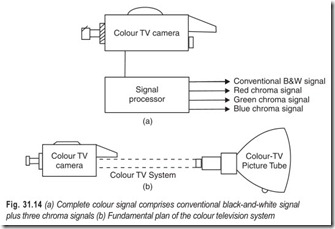
Colour television transmission and reception can be described as a system that reproduces colour images as depicted in Fig. 31.14, that is, a colour scene is scanned and converted into a corresponding video signal by a colour TV camera. In turn this signal is processed through the colour TV system Fig. 31.14(b) and is finally applied to a colour pictue tube. A three-colour picture tube is used to reproduce the colour image.
In its most general aspect a colour TV receiver can be regarded as a conventional black-and-white receiver plus a chroma section and a colour picture tube, as shown in Fig. 31.15. One of the prominent advantages of any of colour television system is its compatibility.
COMPATIBILITY CONSIDERATIONS
An unmodified black-and-white TV receiver cannot reproduce the image carried by a colour video signal in monochrome because the signal does not carry the component corresponding to a black-and-white picture.
But it is possible by suitably adjusting a monochrome receiver, to reproduce one of the colour images (red, green or blue) in black-and-white. However, these cannot replace a black-and-white picture. For compatibility it is, therefore, necessary that in addition to information about colour, the transmitter of a colour television system should send a signal corresponding to black-and-white. This is usually called theluminance signal because the various areas of a black-and-white picture only differ in luminance.
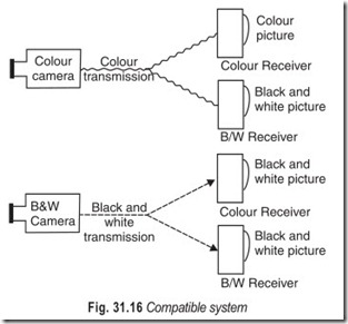
The problem of making the colour and black-and- white programs compatible, now can be better understood. All that is required is to combine the two signals and transmit them together. One signal would contain the luminance or brightness information and the other the chrominance or colour information (hue and saturation). This is shown in Fig. 31.16.
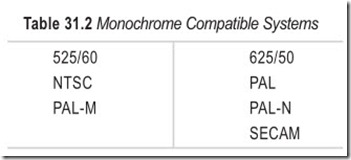
For any two systems to be compatible, they must have the same scanning rate, colour subcarrier frequency and colour encoding technique. Presently, we have five different video systems: NTSC, PAL, PAL-M, PAL-N and SECAM. Some of these are monochrome compatible i.e. ; they can produce black-and-white pictures in the other compatible system. According to compatibility, the systems are divided into two groups with NTSC and PAL-M on one side and PAL, PAL-N and SECAM on the other.
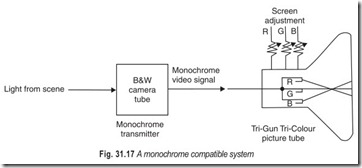
When both the brightness and colour information signals are transmitted a colour picture is produced on a colour receiver. But as a black-and-white receiver does not contain colour circuits, it can display only a monochrome version of the colour transmission. However, since all programs are not broadcast in colour, it is also essential that a colour receiver produce a satisfactory monochrome picture on a monochrome transmission. This is called, reverse compatibility (Fig. 31.17). The need for compatibility dictates the colour systems operate within the same bandwidth as the monochrome system and use the same standards.
If a compatible system is not adopted then the colour transmission will be available to only those viewers who are having colour receivers. The cost involved in the installation of a new set of transmitters just for the sake of colour programs would, no doubt, be prohibitive. These requirements are kept in view by all countries while switching over to colour transmission.
THE NTSC SYSTEM
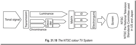
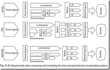
The world’s first commercial colour television system was NTSC (National Television System Committee) introduced in the USA in 1953, and later adopted by Canada, Mexico and Japan. In the NTSC system the two colour difference signals, created by the subtraction of red and blue from the total signal, are not transmitted together, but with one a quarter of a cycle behind the other (in quadrature). The signals are then added together to form a single chrominance signal. When it reaches the receiver, the decoding circuits inside the TV break down the chrominance signal and separate it from its carrier wave. The two signals are then fed into a matrix which then combines them with the luminance signal to recreate the three original colour signals. These then create beams in three electron guns.
The main drawback in the NTSC system is that even slight errors in the phase between the colour difference signals produce errors at the decoding stage so that the set applied too much of one colour; hence the mnemonic for remembering the name “Never Twice the Same Colour”. NTSC receivers have a hue control.
The NTSC system is a simultaneous system which uses quadrature modulation and is compatible with monochrome systems.
THE PAL SYSTEM
The PAL system, which is a refinement of the NTSC system, has been adopted in our country. The PAL system aims to improve the colour picture. The signals are transmitted in the same way, but the receiver delays the information on every line by means of an ultrasonic device for the exact time needed to compare it with the signal for the next line. If, for example, a certain line of the picture, as received, contains too strong a red signal, the system ensures the next line will be too low on red by reversing the polarity of alternate lines. The final information passed to the picture tube is the average of the delayed first line and the corrected second line, so cancelling out the error. No hue control is necessary.
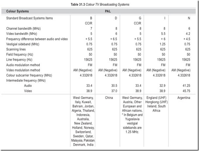
The PAL (Phase Alternate Line) colour TV system may be said to stand midway between the NTSC and SECAM system. The PAL system is explained by the engineers in USA as “Pay for Added Luxury”.The PAL system is not a standard in its own right since the name refers only to the technique used to encode the colour information. PAL standards exist in both the 625/50 (erstwhile German Democratic Republic, UK, Australia and many other all using a 4.43 MHz colour subcarrier) and the 525/60 (the PAL- M system used exclusively in Brazil which has a 3.58 MHz colour subcarrier) scanning frequency standards. There is also a PAL-N version used exclusively in Argentina which is a cross between the 625/50 scanning and 3.58 MHz subcarrier.
PAL is a simultaneous compatible TV system using quadrature modulation. In contrast to SECAM, colour information in the PAL system is transmitted on every line.
Details of the different colour TV broadcasting systems are given in Table 31.3.
THE SECAM SYSTEM
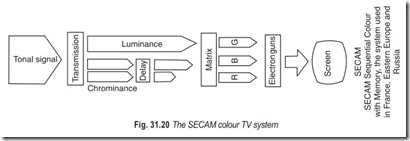
In 1954, Henri De France, a French engineer, published the description of a new colour television system called the “Henri De France System”. However, due to a number of limitations this system did not find practical application. In 1956-1957, it gave way to a new design from which a whole family of systems has grown under the common name of SECAM (Sequential couleur a memoire). It is used in the erstwhile USSR and France.
The SECAM system has a different mode of transmission. The colour difference signals are not arranged a quarter of a cycle apart, but are kept separate by transmitting them on alternate lines of the picture. Delay lines, inside the receiver then hold up one set of signals so that they can be recombined to build a picture from alternate lines of signals from the original scan within the camera. The SECAM system does not, however, give good picture on a black-and-white receiver because it is difficult to separate the signals from their carrier.
In 1960-1961, the SECAM system was further modified to enable the colour difference signals to be frequency modulated onto a subcarrier, which considerably improved the performance of the system. The use of frequency modulation, and the sequential transmission of chrominance signals are the major features of SECAM as distinct from the NTSC system. In a SECAM receiver the chrominance signals are recovered on a time rather than a phase basis, thus rendering any synchronous detectors (as required in the NTSC system) unnecessary. Frequency modulation has made the SECAM system insensitive to amplitude, frequency and phase distortions in the transmission circuit.
SECAM is a compatible colour TV system. Its distinguishing feature is the fact that two colour-difference signals are transmitted sequentially on alternate lines, frequency modulated on a subcarrier while the luminance signal is transmitted on every line.
CONSOLIDATED CCIR SYSTEM-B STANDARDS
Based on Appendix A of IS : 4545–1968.
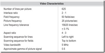
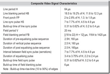
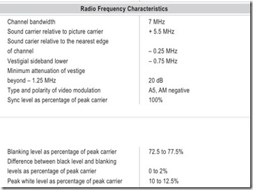
The main characteristics of the CCIR system-B for monchrome television, adopted in India are given below.
BROAD CASTING OF TV PROGRAMS
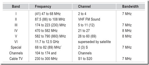
The public television service is operated by broadcasting picture and sound from picture transmitters and associated sound transmitters in three main frequency ranges in the VHF and UHF bands. By international ruling of the ITU, these ranges are exclusively allocated to television broadcasting. Subdivision into operating channels and their assignment by location are also ruled by international regional agreement. The continental standards are valid as per the CCIR 1961 Stockholm plan. The details of the various system parameters are as follows.
Types of Modulation
Vision : C3F (vestigial sideband AM) Vestigial sideband ratios:
0.75 MHz/4.2 MHz = 1:5.6 for system M 525/60, 6 MHz
0.75 MHz/5.0 MHz = 1:6.7 for system B 625/50, 7 MHz
1.25 MHz/5.5 MHz = 1:4.4 for system I 625/50, 8 MHz
The saving of frequency band is about 40%; the ploarity is negative because of the susceptibility to interference of the synchronising circuits of early TV receivers (exception : positive modulation); residual carrier with negative modulation 10% (exception 20%).
Sound : F3E ; FM for better separation from vision signal in the receiver (exception : AM).
Sound carrier above vision carrier within RF channel, inversion at IF ; (exception : standards A, E and, in part, L).
Intermodulation distortion in TV transposers and TV transmitter with common vision-sound amplification and in Cable Television ; 20 : 1 : 0.2 for dual sound broadcast in the B/G standard Channel bandwidth are 5/ 6/7/8/14 MHz depending on standard, conventional values are 6/7/8 MHz and 14 MHz are still valid for a certain transition period.
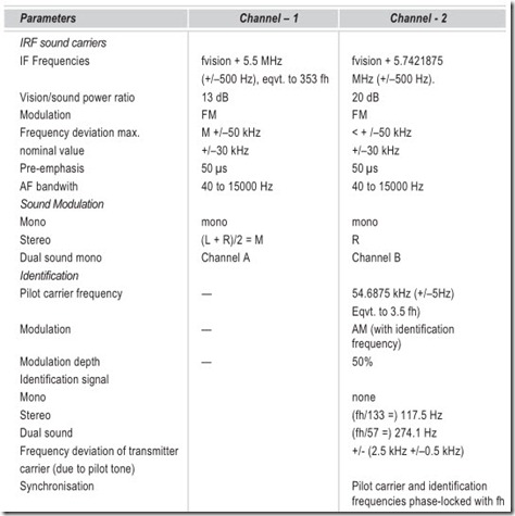
SYSTEM PARAMETERS (FOR STANDARDS B/G)
The two sound channels arrive from the studio via radio link with 15 kHz bandwidth at the TV transmitter, where matrixing is performed for compatibility; (L + R)/2 for channel-1, R for channel-2. An additional sound modulator is used to modulate the second sound carrier with sound channel-2 and with the AM modulated pilot carrier.
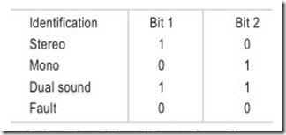
The mode identification is transmitted in (data) line 16 (329) of a normal TV picture from the studio to the dual sound coder of the TV transmitter via the conventional TV lines (i.e. not the sound lines). From the 13 usable words of this data line the first two bits of word 5 are provided for mode identification in bi-phase code as follows :
Vision/sound power ratio is 3 : 1/4 : 1/10 : 1/20 : 1, depending on the standard. Ratios of 5 : 1 and 10 : 1 are conventionally used ; 20 : 1 is used in Germany, its advantage being energy saving.
EXERCISES
Descriptive Questions
1. What are the constituents of white light?
2. Explain the difference in additive primaries and subtractive primaries.
3. What is the difference between a primary colour, secondary colour and complementary colour?
4. Differentiate between hue, brightness and saturation.
5. What is the need for a separate luminance signal?
6. Discuss the relative sensitivity of a three tube camera.
7. How are chrominance signals obtained?
8. What is the difference between a television camera tube and a picture tube?
9. How does the operation of a colour picture tube differ from that of a monochrome picture tube?
10. What are the differences between a delta-gun colour picture tube and an in-line colour picture tube?
11. Briefly explain the working of a colour camera tube.
12. How does a plumbicon differ from a vidicon? Discuss their relative merits and demerits.
13. What are the requirements of a compatible system?
14. How the different television systems have evolved?
15. Give the salient features of the television system used in our country
Multiple Choice Questions
1. The colour which the body presents to the eye is the colour of the light which it
(a) absorbs (b) reflects
2. Primary colours
(a) can be produced by mixing other colours
(b) cannot be produced by mixing othe colours
3. The colours red, green and blue are called
(a) subtractive primaries (b) additive primaries
4. The attributes of colour are
(a) phase (b) hue
(b) amplitude (d) saturation
(e) brightness
1. Monochrome compatible systems can produce pictures in the other compatible system.
2. The main drawback in the NTSC system is that even slight errors in the between the colour difference signals produce erors at the decoding stage.
3. Colour information in the PAL system is transmitted on .
4. PAL standards exist in the system and system.
5. The signal essential to the operation of a black-and-white TV is
(a) chrominance signal (b) luminance signal
(c) composite video signal (d) control signal
6. In the NTSC system, the two colour difference signals are
(a) transmitted together (b) not transmitted together
(c) transmitted in quadrature (d) transmitted in anti-phase
7. Hue control is necesary in the
(a) PAL system (b) NTSC system
(b) SECAM System (d) none of these
8. Colour information in which system is transmitted on every line
(a) PAL (b) SECAM
9. Which television system is used in India
(a) PAL-N (b) CCIR-B
(b) PAL-B (d) PAL-G
Fill in the Blanks
1. White light consists of a mixture of………………………………………….different colours.
2. A………………………………………….colour can be produced by mixing other colours.
3. Hue depends on the………………………………………….wave length of light.
4. The amount of white light contained in a colour determines its………………………………………….level.
5. Brightness of a colour is determined by the amount of………………………………………….contained in it.
6. Brightness is an attribute of…………………………………………..
7. Saturation is an attribute of………………………………………….only.
8. The human eye responds to each of the three primaries…………………………………………..
9. The receiving terminal picks up two colour signals, the third colouring signal………………………………………….is produced by…………………………………………..
10. The generation of the chrominance signal involves the………………………………………….of the luminance signal from the………………………………………….signals.
11. The colour picture tube………………………………………….the primary hues from the televised scene.
12. The colour picture tube has………………………………………….electron guns in one picture tube envelope.
13. The delta gun picture tube has a………………………………………….mask.
14. The quantity of electrons hitting the………………………………………….dots is controlled by their …………………………………………. control grids.
15. The screen of the colour picture tube is coated with………………………………………….different phosphor dots.
16. Some colour picture tubes employ one gun with three………………………………………….cathodes.
17. In the plumbicon camera tube, colours and deflection are both accomplished…………………………………………..
18. The main difference between the plumbicon and the standard vidicon is the…………………………………………..
19. Plumbicon camera tubes are available with a spectral response suitable for any of the colours.
20. For any two systems to be compatible, they must have the same…………………………………………., colour subcarrier frequency and colour………………………………………….techniques.
21. Monochrome compatible systems can produce………………………………………….pictures in the other compatible system.
22. The main drawback in the NTSC system is that even slight errors in the………………………………………….between the colour difference signals produce erors at the decoding stage.
23. Colour information in the PAL system is transmitted on…………………………………………..
24. PAL standards exist in the………………………………………….system and………………………………………….system.
ANSWERS
Multiple Choice Questions
|
1. (b) |
2. (b) |
3. (b) |
4. (b), (d) & (c) 5. (b) |
6. (c) |
|
7. (b) |
8. (a) |
9. (b) & (d) |
Fill in the Blanks
|
1. seven 4. saturation |
2. secondary 5. light energy |
3. dominant 6. white light and colour light |
|
7. colour light 10. separation, natural colour |
8. differently 11. recombines |
9. EG, matrixing 12. three |
|
13. shadow |
14. phosphor, respective |
15. three |
|
16. in-line |
17. magnetically |
18. target |
|
19. primary |
20. scanning rate, encoding |
21. black-and-white |
|
22. phase |
23. every line |
24. 625/50, 525/60 |
