Now that you have mastered the art of developing control cir cuits, you should be ready to analyze circuits developed by some one else. The first step in analysis of a circuit is to determine as much as possible about the operation of the machine or other equipment which the motor drives, so that the functions of the circuit can be more readily understood. To analyze any given circuit, it should be converted to a schematic diagram if one is not available. As stated earlier, if the schematic drawing is properly made, the sequence of operation of control should pro ceed more or less from the upper left of the drawing horizontally across the first line, and then each successive line of the circuit should proceed downward in the drawing. Not all schematics, however, are drawn with this sequence in mind, so do not expect that it will always apply.
7· 1 BASIC PROCEDURE
The basic procedure for circuit analysis is very simple and should be readily understood if you have mastered the preceding chap ter on circuit development. You merely consider the circuit one component at a time and decide what happens if a push button is pushed or a contact closes or opens, realizing that you must have a complete circuit from one line through the coil to the other line in order to energize any relay, contactor, or starter. If the circuit is open at any point, that particular coil will be deenergized and its contacts, wherever they may be found in the circuit, will be in their normal or deenergized position. When the circuit is complete to any particular coil, that contactor, relay, or starter is energized, and its contacts, wherever they may be, are opposite to their normal position. That is, if they are normally closed contacts, they are now open. If they are normally open contacts, they are now closed.
If a time-delay relay is used in the circuit, you must keep in mind whether its contacts are time opening or time closing to determine their normal position and their function in the circuit. When relays are used in the circuit, be sure that you consider every contact which is closed or opened by the relay whenever the coil is energized. Failure to consider one contact of a relay may lead to a misunderstanding of the whole circuit. When analyzing a circuit, be sure that you consider every com ponent in its normal and energized positions so that you under stand the whole operation of the complete circuit. Do not jump to conclusions when halfway through the analysis.
In the following section we shall analyze several circuits, using a step-by-step procedure which should give you the basic funda mentals of this operation so that you can apply it in actual job situations. The ability to analyze a circuit is a prerequisite to any efficient troubleshooting on motor control circuits.
7·2 ANALYSIS OF CIRCUIT 1
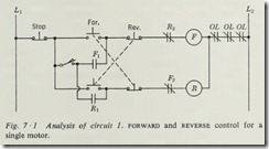
If we look at Fig. 7 ·1, it should be obvious that this is a control circuit for a forward and reverse starter. To analyze the opera tion of this circuit, we shall start with the upper left-hand side at L1. The first component is a STOP button which is normally closed. Therefore, the current may flow through as far as the normally open start button marked FORWARD. Also, the current may flow downward in the wire to the right of the STOP button to a single-pole switch, which is shown in the idle, or OFF, posi tion, and also to the normally open push button marked REVERSE. If now we press the FORWARD button, the current can flow through that button, through the normally closed contact of the REVERSE button, and through the normally closed contact identi fied with the letter R2 to the coil F, which is the contactor
coil for the forward direction. Thence it will proceed through the normally closed overload contacts identified as OL to L2 . The circuit is therefore complete from line 1 through the for- · ward-starter coil to L2, and coil F is now energized . The energiz ing of this coil will open the normally closed contact F2 and close the normally open contact F 1. The opening of the normally closed contact has no immediate effect on the circuit, because the normally open push button for reverse has the circuit broken ahead of this contact. The closing of the normally open contact accomplished no immediate results, because the switch on the line side of this contact is open and there is no voltage present.
When the FORWARD button is released, the circuit from line 1 to coil F is broken at this point and, because there is no maintaining contact around this break in the circuit, the coil will drop out. Suppose now that we close the switch so that it connects line 1 to one side of the normally open contact Fl and again press the FORWARD button. The action of the circuit is the same as previously discussed, except that now when the normally open contact Fl is closed, it completes the circuit from line 1 around the normally open push-button contact. When this push button is released, the circuit is maintained through contact F1 and the motor will continue to run in the forward direction .
Suppose, now, that we press the REVERSE button. It will open its normally closed contact and close its normally open contact. The result of this action will break the circuit to coil F and m ake the circuit through the normally open contacts of the REVE RSE button, through the normally closed contact F, through coil R to line 2, thus plugging the motor from forward to reverse. The running of the motor in reverse is maintained through the normally open contact R 1, which is now closed. The forward starter is prevented from running by the opening of the normally closed contact R. If the switch is thrown to the OFF position and the REVERSE button is pressed, we have exactly the same operation as when we pushed the FORWARD button, except now the reverse starter is momentarily energized.
Now that we have analyzed the operation of the individual components of this circuit, we can sum them up by saying that this circuit provides forward and reverse run . It also provides plugging in either direction and by the position of the switch will also provide jogging in either direction at the will of the operator. The normally closed contacts R2 and F2 are electrical interlock between the forward and reverse starters. The switch shown in this diagram would be known as a jog-run switch be cause in one position it allows the motors to be jogged in either direction and in the other position permits the motor to run in either direction, as desired.
7·3 ANALYSIS OF CIRCUIT 2
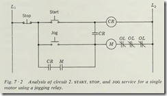
Looking at Fig. 7 ·2, we see only one contactor or starter coil, which would indicate that this is a circuit for the control of a single motor running in only one direction. Again applying our principle of analysis to the circuit to determine its operation, we shall see that the STOP button is normally closed SO current can flow through it to either of two normally open push buttons and a normally open contact identified as CR.
Should we press the START button, it would complete the circuit through the coil identified as CR to line 2. If the designa tions used in this circuit are standard. it is safe to assume that
this is a control relay which apparently has two normally open contacts used in this circuit. These normally open contacts iden tified with the letters CR will now be closed. The one energized· from line I to the STOP button will allow current to flow only as far as the normally open contact labeled M.
The other control relay contact, which connects the wire fol lowing the START button down to the second horizontal line of the diagram, will permit current to flow through this normally open push button, through the now-closed relay contacts to coil M, and through the normally closed overload contacts to line 2, thus energizing coil M and the motor. The energizing of coil
M causes the normally open contact M to close, which will allow current to flow from line 1 through the normally closed STOP button, through the now-closed relay contact CR, through the now-closed contact M, and through coil M, maintaining the circuit to this coil and keeping the motor running even though we release the normally open START button. The motor can be stopped only by pressing the STOP button, which breaks the circuit from L 1, allowing both the control relay and the starter coil to drop out.
Suppose now that we press the second or lower normally open push button, the JOG button. Current will flow directly from line 1 through the normally closed STOP button , through the button we have pressed, to coil M, then through the overloads to line 2, and the motor will be energized. Energizing coil M again closes its normally open contact; but this will not maintain the circuit when the push button is released, because the nor mally open contact CR is open and has the circuit broken from line 1. When we release this push button, the motor is dropped from the line.
This circuit provides jogging with the additional safety pro tection of a relay which definitely prevents the starter from lock ing in during jogging service. When the START button is pressed , both the control relay and the starter are energized, and the starter is locked in through the relay contacts . When the JOG button is pressed, only the starter is energized, and it is definitely prevented from locking in by the normally open relay contacts.
7·4 ANALYSIS OF CIRCUIT 3
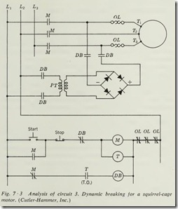
A careful study of Fig. 7 ·3 shows us that the top three horizontal lines contain the line contacts of the starter identified by the letter M, the overload heater elements, and the three motor ter minals identified as Tl , T2, and T3. The next two horizontal lines contain first the contacts DB and then the primary of a transformer identified as PT. The secondary of this transformer is connected to a full-wave bridge rectifier with the d-e terminals marked with a plus and a minus sign. The output of this rectifier is applied to terminals T 1 and T3 of the motor through contacts DB. The part of the circuit so far considered is part of the internal wiring of the controller, and the remaining section of the circuit contains the external start-stop control for the controller.
Considering the balance of this circuit, if we apply our analy sis technique, we will find that pressing the START button will energize coil M because all the other components in this circuit are normally closed. The energizing of coil M will close all its contacts, and, if we consider this in the drawing, the motor will be energized through the closing of the three line contacts. The auxiliary contact in parallel with the START button will close, thus sealing in the circuit and maintaining the motor in the running position. The opening of the normally closed contact M, located in the bottom line of the drawing, will prevent coil DB from being energized.
Simultaneously with the energizing of coil M, coil T is ener gized. This seems to be a time-delay relay because its contact T is indicated to be time opening. If we now press the STOP button, coil M is dropped out along with all its contacts, which will return to their normal positions. The opening of the line contacts M breaks the circuit to the motor and stops the flow of current.
The auxiliary contact in parallel with the START button opens, which has no effect on the circuit at this time. The returning of the normally closed contact M to its closed position, however, will energize coil DB because contact T is still closed. We know that this contact is closed because it is designated to be time opening, and even though its coil is now deenergized, the timer would maintain this contact in a closed position .
With coil DB energized, all contacts indicated by the letters DB will now be in their operating position . The normally closed contact in series with coil M will be open, thus preventing a reenergizing of this coil until the time-delay relay has opened contact T. The closing of the four normally open DB contacts associated with the transformer and rectifier will, in effect, apply d-e voltage to TI and T3 and hold this voltage on the motor until the time-delay relay has timed out, thus opening contact T, which returns the circuit to normal at rest condition.
What is the purpose of applying d-e voltage to a motor when you press the STOP button? The application of d-e voltage to a rotating squirrel-cage motor has the effect of a smooth but positive braking action and will bring the motor to a rapid but very smooth stop. You may wonder why the time-delay relay is necessary in this circuit. If we did not remove the d-e voltage from the motor at almost zero speed, the low d-e resistance of the motor winding would allow excessive current to flow, thus overheating and possibly damaging the motor windings. This time-delay relay should be adjusted so that it will apply the d-e voltage to the motor windings practically down to zero speed and remove it so that the motor comes to an immediate stop.
This circuit seems to provide a normal across-the-line start for a squirrel-cage motor, but in addition provides a rapid, smooth braking effect on its stop. This circuit may well be ap plied to any piece of equipment where a smooth, fast stop is required or where it is desired to have the motor shaft free for manual rot tion when the power is disconnected. It also provides a stop without any tendency to reverse, such as is encountered with a plugging stop. This type of braking is also an advantage where the braking effect must be,applied frequently. It requires less maintenance than a mechanical brake, thus reducing main tenance cost. It also provides less shock to the drive system than a mechanical brake and less heating than with a plugging stop. This type of braking is known as dynamic braking.
7·5 ANALYSIS OF CIRCUIT 4
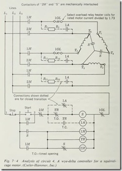
Looking at Fig. 7 ·4, we see a double set of line contacts identi fied as 1M and 2M which connect lines 1, 2, and 3 to the motor terminals. Also in this part of the circuit we have contacts identified as S, which seem to connect some of the motor wind ings. In the lower control section of the diagram, we have a START button, a STOP button, and a coil S, which seems to be some sort of auxiliary contactor. Also, we have coil 1M, which apparently is a line contactor for the motor. Coil TR appears to be a time-delay relay. Coil 2M appears to be a second line contactor for the motor.
In analyzing this circuit, suppose we press the START button,which will energize coil S, since all the contacts and push buttons in this circuit are closed. The energizing of this coil will operate all its contacts, which will energize coil 1M and also will prevent the energizing of coil 2M by the opening of its normally closed
contact. The two normally open contacts S, which connect the three motor terminals, will now be closed, forming a wye con nection for the motor coils. The energizing of coil 1M closes all its contacts, three of which are line contacts for the motor, thus energizing the motor and starting it running. One such contact is in parallel with the START button and acts to maintain the control circuit. Another contact is in series with coil 2M, but at this time it has no effect on the circuit, because the nor mally closed contactS is now open.
At this point, we have a wye-connected squirrel-cage motor running across the line. At the time coil 1M was energized, coil TR was energized, and the timing action of its normally closed contact TR was started. When this contact times out and opens, it breaks the circuit to coil S and returns all its contacts to their normal position. An opening of the two contacts con necting the motor windings breaks the wye connection for the motor windings. The opening of the contact in series with coil 1M has no effect on the circuit, because this circuit is completed through contact 1M in parallel with it. The closing of the nor mally closed contact in series with coil 2M now completes the circuit to this coil and causes its contacts to close, connecting the motor terminals directly to the line, forming a delta connec tion for the motor.
If you have any trouble visualizing these motor connections, you should draw them separately on a sheet of paper to see that the first connection was a wye and the second a delta con nection of the three motor windings. Of course, pressing the STOP button deenergizes all the coils and returns the circuit to its normal at-rest condition. This circuit shows three resistors and three contacts to connect them, along with a coil and other associated contacts which would be necessary to establish a closed transition for the starting of this motor.
Our analysis of this circuit shows that it is a wye-delta-type motor controller used for the purpose of giving a reduced-voltage effect to the starting of this motor as discussed in Chap. 3. In applications where a closed transition is necessary or desirable, the additional connections are shown for adding resistance to bridge the motor connections during the transfer from wye to delta. This is a rather common circuit and deserves some concen trated study as to principle of operation. Again, however, a warning is in order not to memorize this circuit as being the only possible way to give wye-delta starting to squirrel-cage motors. The use of the time-delay relay with its time opening contacts gives us a definite-time type of acceleration for this con trol circuit. This controller, as you may have noticed, involves a two-pole and two three-pole magnetic contactors along with the necessary mechanical interlock to assure a sequence of opera tion and to prevent two connections at the same time, which would cause a short circuit.
7 ·6 ANALYSIS OF CIRCUIT 5
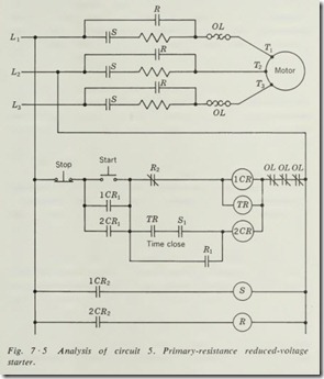
Considering the circuit of Fig. 7 ·5, we find that the resistance in series with the motor leads would seem to indicate that this is a primary-resistance reduced-voltage starter. Looking at the control section of the diagram, we have what seems to be an ordinary three-wire control circuit to energize coils lCR and TR. If we press the START button, current may flow through the normally closed STOP button, the START button and contact R2, and coils lCR and TR will be energized. The energizing of coil 1CR will cause all its contacts to close. Contact 1CR 1 is in parallel with the START button and will perform the function of maintaining the circuit to the coil. Contact 1CR2 will close and energize coil S. The energizing of this coil will cause the line contacts S to close and will energize the motor through the series resistances. The presence of resistance in series with the motor leads will cause a reduced voltage to be applied to the motor, thus reducing the inrush current to the motor and providing reduced-voltage starting.
The motor is now accelerating under reduced voltage, and the time-delay relay TR is timing out. When relay TR times out, it will close contact TR. When this contact closes, it will energize coil 2CR because contact Sl is closed by coil S. The energizing of coil 2CR will cause contact 2CR I to close. This contact is in parallel with the START button and forms an addi tional maintaining circuit for the coil. The closing of contact 2CR2 causes coil R to be energized, closing the line contacts identified as R. These contacts are in parallel with the resistors
and effectively short them out of the circuit, thus applying full line voltage to the motor, which will enable it to accelerate to its full speed and run across the line.
The energizing of coil R also closes contact R 1, which is in parallel with contacts TR and Sl. The opening of contact R2 will cause the dropping out of coils 1CR and TR. The con tacts associated with these two coils will now return to their normal position, and we shall have the motors running through the control circuit, which consists of the STOP button, contact 2CR 1, contact R 1, and coil 2CR. This circuit maintains the circuit to the run coil through contact 2CR2. Should the STOP button now be pressed, all contacts would return to their normal position and all coils would be deenergized , thus opening the line contacts to the motor, and the motor would come to a stop.
This circuit obviously is one for a primary-resistance reduced voltage starter. Again it must be pointed out that this is only one of the many arrangements of coils and contacts which could be used to achieve the same results. Different manufacturers will use variations of a similar circuit in the control of their starters, but the ba sic principle of operation is the same if a definite-tim e sequence of starting is employed.
This circuit could be expanded to give several more stages of acceleration by the addition of more units of resistance in series with the motor, with a control relay and a time-delay relay for each step or stage of acceleration . This is a two-stage, or two-step, starter, since it provides two steps of acceleration , one under reduced voltage and one under full voltage.
The only critical adjustment in this circuit will be found in the time-delay relay TR, which must not be allowed to maintain the motor under reduced voltage longer than the time it takes to accelerate to its maximum speed under reduced-voltage condi tions. Prolonged operation of the motor under reduced voltage may quite possibly overheat and damage the motor windings and cause the resistance elements to be seriously damaged or burn out.
This controller consists of a start contactor S, which must be three-pole, and a run contactor R , which also must be three pole. In addition to the two contactors, there are two control relays and one time-delay relay. This equipment would be found generally mounted in one enclosure with the START-STOP station either mounted on the door of this enclosure or separately wired to any convenient location in the building.
At this stage in your study of controls and analysis of control circuits, you should consider a circuit from the standpoint of what would happen if a particular coil burned out or a particular contact failed to open or close, as the case may be. For instance, suppose that the time-delay relay TR were to have a burnt-out coil. What would be the effect on this circuit? The circuit would function up through the closing of the start contactor S, and the motor would be energized under reduced-voltage conditions. If contact TR does not close, however, then the second control relay cannot be energized and the run contactor cannot be ener gized. Thus, the motor would continue to run under reduced voltage conditions. The current under this condition is such that it will open the overload relay contacts and will drop out coil lCR, thus stopping the motor and returning it to its normal position. These overload units should be manual-reset units so that the operator will have to reset them and determine the cause of trouble before restarting the motor. This control circuit will give overload protection and incomplete sequence protection (Sec. 2 ·15).
7 ·7 ANALYSIS OF CIRCUIT 6
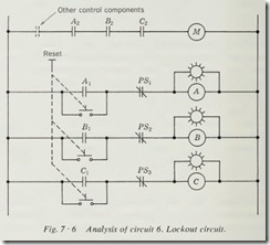
The circuit of Fig. 7 ·6 is a partial circuit used to illustrate a lockout circuit, which is extensively used where malfunction of some part of the equipment must require attention by the opera tor before the equipment is restarted. Looking at the circuit of Fig. 7 ·6, you will see dotted a contact which represents the normal control components such as START and STOP buttons, limit switches, or other devices which normally start and stop the machine. This circuit concerns itself only with the lockout components. The normally closed contacts represented as PSl, 2, and 3 are pressure switches which will open only when the required pressure is not maintained in their particular part of the machine or process. Coils A, B, and C are relay coils paral leled by pilot lights.
To start the operation of this equipment, it is necessary to press the RESET button, which will close the three associated and mechanically interlocked switches. The three relays will be energized, thus closing their normally open contacts. Contacts A 1, B 1, and C 1 are used to maintain the coil circuit. Contacts A 2, B2, and C2 are maintained in their closed position as long as the operation of the pressure switches is normal, thus enabling the normal control components to energize coil M at will. If
the pressure drops or rises, as the case may be, from its normal value at any one of the three places where pressure switches are located, it will open one of the normally closed contacts. For instance, if PSI opens, coil A will be deenergized, which will open contact A 2 and drop out the motor. At the same time, contact A 1 will open. If the proper pressure returns to pressure switch 1, its contact will close but coil A will not be reenergized, because the circuit is broken at contact A 1. The pilot light in parallel with this coil will be out and will indicate which of the protective circuits is not functioning. The operator will know that pressure switch 1 was the cause of the shutdown of the equipment. In order to restore the machine to operation, the pressure sensed by pressure switch 1 must be restored to normal. Then the RESET button must be pressed in order to energize coil A, thus closing its contacts and allowing the normal operation of the control circuit. Of course, the same procedure will apply to the second and third pressure switches and asso ciated contacts and coils.
This type of circuit is generally applied to fully automatic equipment, where the machine or process is allowed to start and stop by itself under the control of pilot devices which sense the condition of the process or material as the machine does its work. When machinery operates under these conditions, it is generally desirable to have some means to stop the process whenever a malfunction occurs and to prevent it from restarting until it has received the attention of an operator.
Summary
The preceding circuits and their analysis should form a basis upon which you can build a skill of analyzing circuits as found in everyday use in industry and on the job. While these circuits
do not in any way represent all or even a major part of the possibilities in motor control, the procedure and method of analyzing their operation, if properly understood , may be applied to any and all control circuits and followed through to a com plete understanding of the operation of the equipment and con trol components associated with it.
The student who wishes to obtain proficiency in control will apply these basic principles to other circuits which are at his disposal until he is satisfied that he can, with reasonable speed , interpret and analyze control circuits of all types .
The danger in circuit analysis lies in the tendency to j ump to conclusions, that is, to decide what the circuit does and how it operates when you have analyzed only a fraction of all of its possibilities. Learn to study a circuit contact by contact and coil by coil until you have completely traced its operation through its normal sequence f rom beginning to end, and you will save many headaches in the future.
There are no review questions at the conclusion of this sec tion. The procedure you should follow is to obtain additional circuits and practice analyzing them until you obtain proficienc y. The mark of distinction between a good troubleshooter and a poor troubleshooter generally lies in the ability to analyze the control circuit and determine quickly which of the many compo nents could cause the malfu nction of the machine which he is trying to correct.
