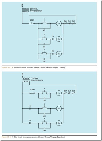
Sequence Control Circuit #3
A third circuit that is almost identical to the previous circuit is shown in Figure 31 – 3. This circuit also employs the use of normally open auxiliary contacts to prevent motor #2 from starting before motor #1, and motor #3 cannot start before motor #2. These normally open auxiliary contacts that control the starting sequence are often called permissive contacts because they permit some action to take place. The main difference between the two circuits is that in the circuit shown in Figure 31 – 2, the stop push button interrupts the power to all the motor starters. The circuit in Figure 31 – 3 depends on the normally open auxiliary contacts reopening to stop motors #2 and #3.
Related posts:
MATCHING IMs TO VARIABLE SPEED/TORQUE LOADS
HUMAN–MACHINE INTERFACES:HUMAN–MACHINE INTERACTIONS
Audio Amplifier Performance:A Brief History of Amplifiers
Integrated Circuits:handling of Integrated circuits
Electronics Explained – Industrial Control
Fixed Appliance and Socket Circuits:Continuity of Ring Circuit Conductors
Introduction to Electrohydraulic Servo Motors
Stepping Motors:Four-Step Switching (Full Stepping)
Amplifier Applications:Direct-coupled Amplifiers
Inductive Reactance
FUNDAMENTALS OF ELECTRIC SYSTEMS:LENZ’S LAW
Signal-carrying switches:Digital switching
MAINTENANCE OF MOTORS:ENCLOSURES AND COOLING METHODS
Emission Control Systems part2
