Digital switching
The switching of digital signals is a more specialized topic than analogue switching because of the range and nature of digital signals. Excluding the switching of supply voltages, switching actions for digital circuits can be of three separate types. First of all, a switch may be used to provide a signal into the circuit. An example of this is a push button used to allow a digital circuit to operate step by step. Another use is to select parameters for the digital circuit, such as the use of DIL switches in devices, such as computer printers, to set up the way that the machine operates. The third method is the switching of digital signals on lines from one unit to another, like the ‘T-switches’ used to allow one computer to control one of two different printers. This last type of switching can make use of the same types of FET switches as are used for analogue switches, but the way that the switches are used may be different. It is usually undesirable to switch over a digital circuit while the voltages are active, so this type of switch is likely to make use of an inhibit pin. ;\’hile any line is active, a voltage can be generated to keep the inhibit pin at its inhibit level so that the switch will not operate until all the switched lines are at zero level.
Control switches for digital work are generally simple DIL types, usually in banks of eight. Their switching action is on DC voltages only, although the DC voltage does not necessarily control the digital circuit directly. Instead, the circuit interrogates the switch settings at the time when the operating voltage is first applied, and the settings that exist at that instant are used from then on. Changing a switch position in such a digital circuit will not therefore cause any effect until the circuit has been switched off and then on again. This avoids the effects, possibly catastrophic, of unintentional operation of these setting switches while the circuit is active.
The most critical application is for switches that cause a signal input, usually in the form of a push-button switch that delivers a single pulse when pressed. The problem here is that no simple mechanical switch delivers a single voltage change, because the elastic nature of the contacts means that contacts will make, then bounce apart and remake at least once, delivering a multiple pulse. Contact bounce in switches that handle
analogue signals will cause noise, mainly impulse noise, but in digital circuits it can cause total failure of the switch action. If the switch is meant to be used to show the digital action step by step, it is hardly very useful if the steps are sometimes single, sometimes double, sometimes triple. Since the bounce is almost unavoidable (although mercury-wetted reed switches are almost bounce-free) the methods used to eliminate the bounce must be electronic.
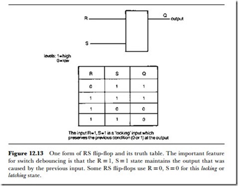
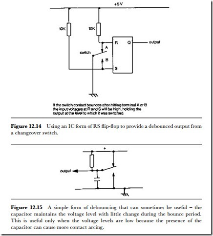
The main method is the use of an RS-type flip-flop. The characteristics of such a flip-flop are shown in Figure 12.13, and the important point is that the output does not change while the inputs are at the same voltage. In the circuit shown in Figure 12.14, then, the bounce of the switch will only serve to hold the output voltage at its changed level, rather than allowing the voltage to change back. It is unusual to find switches sold together with debouncing circuitry, and the problem of debouncing is usually left to the designer.
In some cases (when the switch bounce time is very short) a simple resistor-capacitor circuit of the type illustrated in Figure 12.15 can be used. This relies on the bounce time being short compared to the RC time constant, so that the voltage level cannot change by much during the time when the switch contacts bounce open. If a switch that uses such a debounce circuit has to be replaced, then it must be replaced by a switch with identical or very similar bounce characteristics. This is seldom easy,
because the bounce characteristics of switches are seldom documented, and specialized equipment (such as a storage or digital oscilloscope) is needed to measure these characteristics.
Digital equipment that makes use of signal-input switches will not neces- sarily incorporate any visible switch debouncing, however, in the form of ICs or other circuits. This is because the debouncing of a switch can be carried out by the operating software of a microprocessor circuit. The opening of the switch can be detected in two different ways, described as polling or interrupt. In the polling system, the state of the switch (open or closed) is checked at intervals, and if this state changes it is rechecked to find if the change is permanent. In this way, the closing of a switch causes
no bounce problems because the switch closure has no effect until the polling check reports that the switch has been found closed on two, possibly more, consecutive readings.
The other method uses the closing of the switch to send a signal to the microprocessor, which then interrupts whatever it is processing at that instant. The switch state is then checked, and checked again after an interval longer than the bounce time, and the latter state taken as its final state. In each case the time delay, which is the important feature of any debouncing system, is obtained by a part of the microprocessor software. If problems arise due to insufficient debouncing (such as double letters from a keyboard when a letter key has been struck sharply once), then the remedy is usually a modification to the software, and this may have to be in the form of a patch, a piece of added software, rather than a permanent change. The main problems of this type arise with computer keyboards, of which the old TRS-80 Mark 1 was a notorious example, although many older machines of the PC class were prone to give bounce effects, mainly on the ‘n’ and ‘m’ keys.

