14-to-10 digital companding
A 14-bit digitiser provides 16,384 quantum levels, which is adequate for high-quality sound reproduction. If fewer than 14 bits are used, the quantising error can become audible in the form of a ‘gritty’ quality for low-level signals, an effect known as granular distortion.
The use of 32 kHz sampling with a coding accuracy of 14 bits per sam- ple would require a data bit rate of approximately 1 Mbps, and conse- quently a very large bandwidth which could not be accommodated within a single TV channel. For this reason, near instantaneous digital compand- ing is used, which enables the number of bits per sample to be reduced from 14 to 10 with virtually no degradation in the quality of sound repro- duction. Consequently, the data bit rate of the system is markedly reduced.
Unlike the analogue companding described earlier, which has the aim of improving the signal-to-noise ratio (SNR), the purpose of digital com- panding is to reduce the number of bits per sample. Furthermore, because all the operations of digital companding are performed in digital form, the compressor at the transmitting coding stage and the expander at the encoder receiving stage can be matched precisely, without the mist rack- ing that is associated with analogue companding.
The companding technique used in NICAM is based on the fact that the significance of each bit of a binary code depends on the sound level which the particular sample code represents. For instance, assuming a peak analogue input of 1 V, then with a 14-bit code the quantum step is given by quantum step = 1V/quantum levels = 1V/16, 384 = 61JlV
This is the value of the least significant bit (LSB). The second LSB has a value of 2 X 16 = 32 JlV, and so on. It can readily be seen that for a loud sound, i.e. a high-amplitude sample, say 500 mV or over, the effect of the three or four LSBs is imperceptible and may be neglected. However, for delicate or quiet passages with sample amplitudes in the region of a few hundred microvolts, the LSBs are all important. NICAM companding reduces the 14-bit sample codes to 10-bit codes in such a way that for low-level signals the receiver is able to recreate the original 14-bit samples, and for high-level signals it is possible to discard between one and four LSBs as irrelevant.
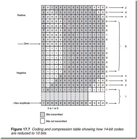
Each segment of 32 successive audio samples is investigated to find the largest sample in that segment. The amplitude of this sample is then used to indicate the audio strength of the whole segment in five coding ranges (Figure 17.7). Coding range 1 represents a segment where the largest sample falls between the maximum amplitude and one-half the maximum amplitude, range 2 is from one-half to one-quarter maximum amplitude, range 3 is from one-quarter to one-eighth, range 4 is from one-eighth to one-sixteenth and range 5 represents one-sixteenth of maximum amplitude to zero or silence. The shaded bits in Figure 17.7 show the bits actually transmitted for each range. In each case the most significant bit, the 14th, is the sign bit and is therefore retained to indicate a positive or negative value. The 13th bit is discarded if it is the same as the 14th, the 12th is likewise discarded if it is the same as the 13th and 14th, and similarly with the 11th and 10th bits. Where high-order bits are discarded, NICAM provides a labelling technique known as scale factor coding, which enables the missing bits to be reconstituted at the receiver. When the
discarding of the high-order bits is completed, coded samples of between 10 and 14 bits are left, depending on the sequence of the high-order bits. Where a code has more than 10 bits, a sufficient number of bits are removed to reduce the size of the code to 10 bits; the first bit to be removed is the LSB and successive bits are removed by working upwards.
It follows, therefore, that for a segment of 32 samples falling in the largest amplitude range, range 1, the four LSBs of each sample are dis- carded and lost for ever. In the case of segments falling in range 2, the bit next to the most significant bit, the 13th bit of each sample, is discarded along with the three LSBs. Although the three LSBs are lost, the 13th bit is reconstituted at the receiver, since it always has the same value as the most significant bit, and so on for ranges 3, 4 and 5.
The next stage is the addition of the parity bit to each sample code, resulting in an 11-bit word. One parity bit is added to the 10-bit sample to check the six most significant bits (MSBs) for the presence of errors. The remaining bits, the five least significant one, are transmitted without a parity check. Even parity is used for the group formed by the six most sig- nificant bits. Subsequently, the parity bits are modified to introduce greater error protection and correction as well as coding range information.
The decoder at the receiving end needs to know the number of high-order bits that have been discarded, so they may be reinserted. This is carried out by labelling each coding range with a code known as the scale factor. The scale factor is a 3-bit code which informs the decoder of the number of dis- carded high-order bits. To save on bandwidth, this information is conveyed without the use of additional bits. Instead, the information is inserted by modifying the parity bits, a technique known as signalling-in-parity.
