Synchronisation pulses
The receiver or monitor which we shall use to display the picture has scan- ning waveform generators which must run in perfect synchronism with the readout of the image sensor at the transmitting end. This ensures that the video information picked up from the sensor is reproduced in the right place on the display. Plainly, if the camera sees a spot of light in the top right-hand corner of the picture and the monitor’s scanning spot is in the middle of the screen when it reproduces the light, the picture is going to be jumbled up!
This is prevented by inserting synchronising pulses (sync pulses for short) into the video waveform at regular intervals, and with some distin- guishing feature to enable the TV monitor to pick them out. Synchronising pulses are introduced at the end of each line to initiate the line flyback at the receiver; these pulses are called the line sync. Another set of synchro- nising pulse is introduced at the end of a field to initiate the start of the field flyback; this is called the field sync.
Composite video waveform
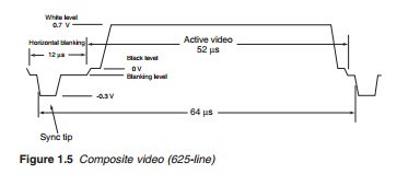
The picture information and the sync pulse of a single line constitute what is known as the composite video waveform. Each line is made up of the active video portion and the horizontal blanking portion. As shown in
Figure 1.5, the picture information is represented by the waveform between the two-line sync pulses and thus may acquire any shape, depending on the varying picture brightness along the line. The waveform shown represents a line at peak white (maximum brightness).
Before and after every sync pulse, the voltage is held below the black level as shown for short periods of time, known as the front porch and the back porch, respectively. The front porch has a duration of 1.55 J.s; it ensures the video brightness is completely blocked before the sync pulse is applied. The back porch has a longer duration of 5.8 J.s; it provides time for the flyback to occur before the application of the video information. The back porch is also used for black level clamping. As can be seen, the front porch, the sync pulse and the back porch are at or below the black level. During this time, a total of 12.05 J.s, the video information is com- pletely suppressed; this is known as the line blanking period.
The total available peak-to-peak voltage of 1 V is divided into two regions:
● Below black level region 0 to -0.3 V reserved for the sync pulses (line and field)
● Above black level region 0–0.7 V (peak white), used for the video or picture information
The duration of one complete line of a composite video may be calculated from the line frequency:
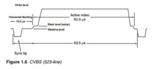
The composite video waveform consists of video, blanking and sync pulse, hence it is more commonly known as composite video, blanking and sync, CVBS.
The equivalent CVBS waveform and timings for the 525-line NTSC system is shown in Figure 1.6 with a line duration of 63.5 J.s and active video duration of 52.6 J.s.
Newnes Guide to Television and Video Technology


